METER / GAUGE SYSTEM Tachometer Malfunction
DESCRIPTION
In this circuit, the combination meter assembly receives engine speed signals from the ECM using the CAN communication line. The combination meter assembly displays the engine speed, which is calculated based on the data received from the ECM.
WIRING DIAGRAM
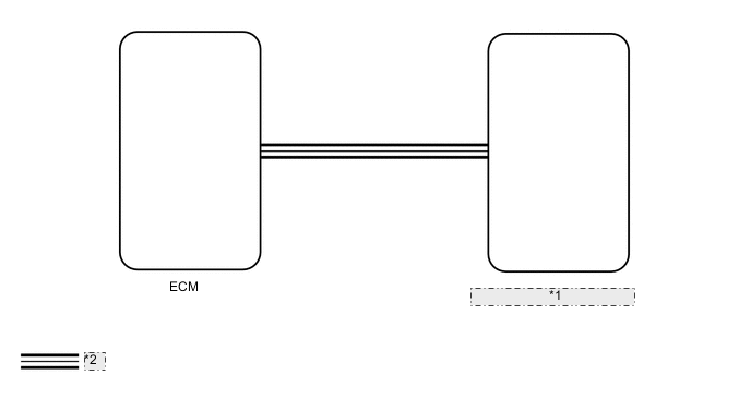
| *1 | Combination Meter Assembly |
| *2 | CAN Communication Line |
CAUTION / NOTICE / HINT
Note
When replacing the combination meter assembly, make sure to replace it with a new one.
PROCEDURE
-
CHECK FOR DTC
-
Check for DTCs.
OK DTCs U0100, U0129, U0131, U0142, U0151, U0163, U023A and U1104 are not output. Result Proceed to OK NG
NG 
GO TO CAN COMMUNICATION SYSTEM for LHD with Central Gateway ECU: Click here for RHD with Central Gateway ECU: Click here for LHD without Central Gateway ECU: Click here for RHD without Central Gateway ECU: Click here
OK 
-
-
CHECK SFI SYSTEM OR ECD SYSTEM
-
*1: Engine Type Gasoline
-
*2: Engine Type Diesel
-
Check if a SFI system*1 or ECD system*2 DTC is output.
ECD system (2AD-FHV): Click here
ECD system (2AD-FTV [for CCo]): Click here
ECD system (2AD-FTV [for DPF]): Click here
ECD System (2WW): Click here
SFI system (2AR-FE [w/ Canister Pump Module]): Click here
SFI system (2AR-FE [w/o Canister Pump Module]): Click here
SFI system (3ZR-FAE): Click here
SFI system (3ZF-FE [for K111, K111F]): Click here
SFI system (3ZF-FE [except K111, K111F]): Click here
Powertrain > Engine and ECT > Trouble CodesOK DTC is not output Result Proceed to OK NG (Engine Type Gasoline) NG (Engine Type Diesel)
NG (Engine Type Gasoline)
GO TO SFI SYSTEM for 2AR-FE (w/ Canister Pump Module): Click here for 2AR-FE (w/o Canister Pump Module): Click here for 3ZR-FAE: Click here for 3ZR-FE (for K111, K111F) : Click here for 3ZR-FE (except K111, K111F) : Click here
NG (Engine Type Diesel)
GO TO ECD SYSTEM for 2AD-FHV: Click here for 2AD-FTV (for CCo): Click here for 2AD-FTV (for DPF): Click here for 2WW: Click here
OK
-
-
PERFORM ACTIVE TEST USING GTS (TACHOMETER OPERATION)
-
Using the GTS, perform the Active Test.
Body Electrical > Combination Meter > Active TestTester Display Measurement Item Control Range Diagnostic Note TachoMeter Operation Tachometer OFF, 0, 1000, 2000, 3000, 4000, 5000, 6000 or 7000 (rpm) -
Body Electrical > Combination Meter > Active TestTester Display TachoMeter Operation OK Tachometer indication is normal. Result Proceed to OK NG
NG
REPLACE COMBINATION METER ASSEMBLY Click here
OK
-
-
READ VALUE USING GTS (ENGINE RPM, ENGINE SPEED)
-
Using the GTS, read the Data List.
Body Electrical > Combination Meter > Data ListTester Display Measurement Item Range Normal Condition Diagnostic Note Engine Rpm Engine speed Min.: 0 rpm, Max.: 12750 rpm Actual engine speed -
Powertrain > Engine and ECTTester Display Measurement Item Range Normal Condition Diagnostic Note Engine Speed Engine speed Min.: 0 rpm, Max.: 16383 rpm 750 to 850 rpm: Idling with warm engine -
Powertrain > Engine > Data ListTester Display Measurement Item Range Normal Condition Diagnostic Note Engine Speed Engine speed Min.: 0 rpm, Max.: 16383 rpm 750 to 850 rpm: Idling with warm engine -
Body Electrical > Combination Meter > Data ListTester Display Engine Rpm
Powertrain > Engine and ECT > Data ListTester Display Engine Speed
Powertrain > Engine > Data ListTester Display Engine Speed Tech Tips
-
When the Data List values of the ECUs match, an internal malfunction of the ECM is suspected.
-
When the Data List values of the ECUs do not match, a signal output error of the ECM or an internal malfunction of the combination meter assembly is suspected.
Result Proceed to The Data List values of the ECUs do not match The Data List values of the ECUs match -
The Data List values of the ECUs do not match
REPLACE COMBINATION METER ASSEMBLY Click here
The Data List values of the ECUs match
-
-
CHECK COMBINATION METER ASSEMBLY
-
Replace the combination meter assembly with a new or normally functioning one.
-
CHeck that the operation of the tachometer returns to normal.
OK The operation of the tachometer returns to normal. Result Proceed to OK NG
OK
END (COMBINATION METER ASSEMBLY WAS DEFECTIVE)
NG
REPLACE ECM for 2AD-FHV: Click here for 2AD-FTV: Click here for 2AR-FE: Click here for 2WW: Click here for 3ZR-FAE: Click here for 3ZR-FE: Click here
-