ENGINE ASSEMBLY REMOVAL
CAUTION / NOTICE / HINT
The necessary procedures (adjustment, calibration, initialization, or registration) that must be performed after parts are removed, installed, or replaced during the engine assembly removal/installation are shown below.
| Replaced Part or Performed Procedure | Necessary Procedure | Effect/Inoperative Function when Necessary Procedure not Performed | Link |
|---|---|---|---|
| Auxiliary battery terminal is disconnected/reconnected | Memorize steering angle neutral point | Lane-keeping assist system (for Mono camera type) | for Stereo Camera type: for Mono Camera type: |
| Lane control system (for Stereo camera type) | |||
| Parking support brake system*1 | |||
| Pre-collision system (for Mono camera type) | |||
| Pre-collision system (for Stereo camera type) | |||
| AFS (Front-lighting adaptive system) | |||
Lighting system (EXT) |
|||
| Variable gear ratio steering system | |||
| Parking assist monitor system | |||
| Panoramic view monitor system | |||
| Initialize rear door sunshade system | Rear door sunshade system | ||
| Initialize power trunk lid system | Power trunk lid system | ||
| Replacement of ECM | Vehicle Identification Number (VIN) registration | DTC P063051 is output | w/ Canister Pump Module w/o Canister Pump Module |
|
Inspection after repairs |
|
w/ Canister Pump Module w/o Canister Pump Module |
| Replacement of engine assembly | Inspection after repair | ||
| Drive learning*2 |
|
L310: L310F: |
|
| Parts between the steering wheel and tires have been removed/installed, replaced or adjusted | Perform Actuator Angle Neutral Point Calibration and Initialization |
|
|
| Front bumper assembly (Including removal and installation) |
|
Parking support brake system | |
| Front television camera view adjustment | Panoramic view monitor system | ||
| Suspension, tires, etc |
|
Parking support brake system | |
|
Panoramic view monitor system | ||
| Rear television camera assembly optical axis (Back camera position setting) | Parking assist monitor system |
Click here Click here
*2: After performing the confirmation driving pattern, if the shock during acceleration is large after calibrating the "A/T Code Reset", perform driving learning.
CAUTION:
-
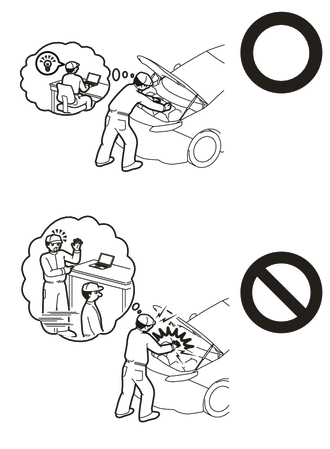
This vehicle has contains high voltage circuits standardized with orange colored wiring and connectors, so follow the instructions in this manual to perform the procedures correctly.
-
If the correct procedures are not followed according to the instructions in this manual, there is a danger of electric shock from the high voltage circuits.
-

Be sure to wear insulating gloves when working on high voltage wiring or components.
-
If work is performed without wearing insulating gloves, there is a danger of electric shock.
-
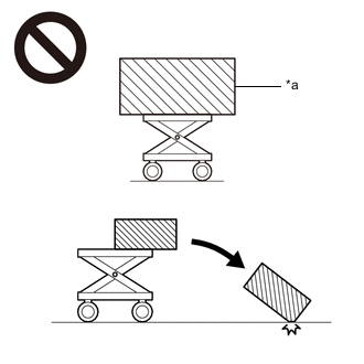
*a An Object Exceeding Weight Limit of Engine Lifter The engine assembly with transaxle is very heavy. Be sure to follow the procedure described in the repair manual, or the engine lifter may suddenly drop or the engine assembly with transaxle may fall off the engine lifter.
-
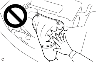
To prevent burns, do not touch the engine, exhaust manifold or other high temperature components while the engine is hot.
PROCEDURE
-
PRECAUTION
Note
After turning the power switch off, waiting time may be required before disconnecting the cable from the battery terminal. Therefore, make sure to read the disconnecting the cable from the battery terminal notice before proceeding with work.
-
HEIGHT OFFSET
-
REMOVE LUGGAGE COMPARTMENT MAT SUB-ASSEMBLY
-
DISCHARGE FUEL SYSTEM PRESSURE
-
DISCONNECT CABLE FROM NEGATIVE AUXILIARY BATTERY TERMINAL
Note
When disconnecting the cable, some systems need to be initialized after the cable is reconnected.
-
PARKING LOCK FORCED RELEASE
-
REMOVE INVERTER COVER ASSEMBLY RH (for LHD)
-
REMOVE INVERTER COVER ASSEMBLY LH (for RHD)
-
REMOVE RADIATOR COVER PLATE
-
REMOVE UPPER RADIATOR SUPPORT SEAL
-
REMOVE LOWER RADIATOR AIR DEFLECTOR
-
REMOVE NO. 1 AIR CLEANER INLET
-
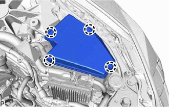
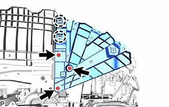
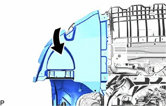
REMOVE V-BANK COVER SUB-ASSEMBLY
-
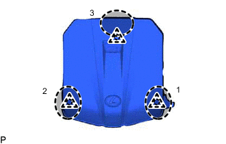

Areas to place hands when lifting cover Lift the V-bank cover sub-assembly to detach the 3 clips in the order shown in the illustration, and remove the V-bank cover sub-assembly.
Note
If the V-bank cover sub-assembly is lifted rearward or forward and to the right or left at the same time, the V-bank cover sub-assembly may be damaged.
-
-
REMOVE SERVICE PLUG GRIP
-
CHECK TERMINAL VOLTAGE
-
RECOVER REFRIGERANT FROM REFRIGERATION SYSTEM
-
for HFC-134a (R134a):
-
for HFO-1234yf (R1234yf):
-
-
PLACE FRONT WHEELS FACING STRAIGHT AHEAD
-
REMOVE FRONT WHEEL
-
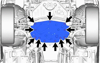
REMOVE NO. 1 ENGINE UNDER COVER ASSEMBLY (for 2WD)
-
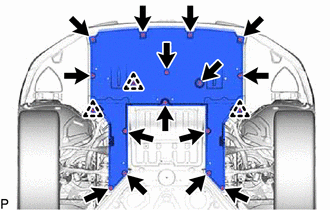
Remove the 15 screws, 3 clips and No. 1 engine under cover assembly.
-
-
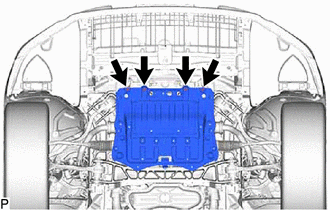
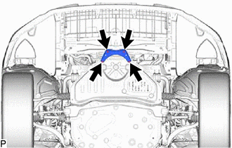
REMOVE TRANSMISSION UNDER COVER (for 2WD)
-


Screw 
Bolt Remove the 2 bolts, 2 screws and transmission under cover.
-
-
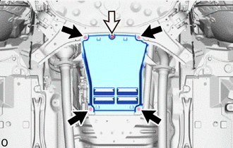
REMOVE NO. 2 ENGINE UNDER COVER ASSEMBLY (for 2WD)
-
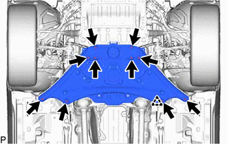
Remove the 10 bolts, clip and No. 2 engine under cover assembly.
-
-
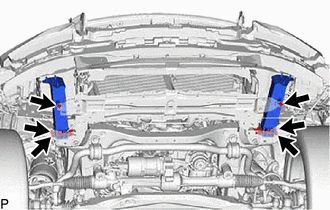
REMOVE FRONT SUSPENSION MEMBER BRACE (for 2WD)
-

Remove the 4 bolts and front suspension member brace.
-
-
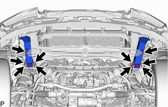
REMOVE STRUT BAR BRACKET SUPPORT SUB-ASSEMBLY (for 2WD)
-
Remove the 4 bolts and strut bar bracket support sub-assembly.
-
-
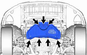
REMOVE NO. 1 ENGINE UNDER COVER ASSEMBLY (for AWD)
-
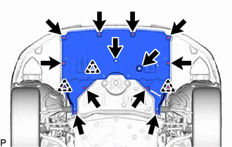
Remove the 12 screws, 3 clips and No. 1 engine under cover assembly.
-
-
REMOVE TRANSMISSION UNDER COVER (for AWD)
-
Screw Bolt Remove the 4 bolts, screw and transmission under cover.
-
-
REMOVE NO. 2 ENGINE UNDER COVER ASSEMBLY (for AWD)
-
Remove the 11 bolts, and No. 2 engine under cover assembly.
-
-
REMOVE FRONT SUSPENSION MEMBER BRACE (for AWD)
-
Remove the 4 bolts and front suspension member brace.
-
-
REMOVE STRUT BAR BRACKET SUPPORT SUB-ASSEMBLY (for AWD)
-
Remove the 7 bolts and strut bar bracket support sub-assembly.
-
-
DRAIN ENGINE OIL
-
DRAIN ENGINE COOLANT
-
DRAIN COOLANT (for Inverter)
-
DRAIN HYBRID TRANSMISSION FLUID
-
for 2WD:
-
for AWD:
-
-
DRAIN DIFFERENTIAL OIL (for AWD)
-
REMOVE RADIATOR SUPPORT TO CROSSMEMBER BRACE SUB-ASSEMBLY LH
-
REMOVE RADIATOR SUPPORT TO CROSSMEMBER BRACE SUB-ASSEMBLY RH
-
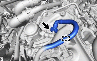
DISCONNECT NO. 2 PCV HOSE
-
REMOVE AIR CLEANER WITH AIR CLEANER HOSE
-
REMOVE INVERTER TERMINAL COVER
-
DISCONNECT MOTOR CABLE
-
DISCONNECT GENERATOR CABLE
-
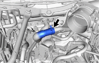
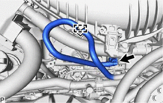
DISCONNECT NO. 1 FUEL VAPOR FEED HOSE
-
Disconnect the No. 1 fuel vapor feed hose from the purge VSV.
-
-
DISCONNECT NO. 1 RADIATOR HOSE
-
DISCONNECT NO. 3 RADIATOR HOSE
-
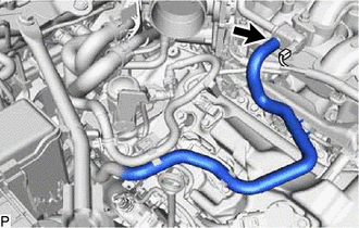
DISCONNECT INLET HEATER WATER HOSE
-
Slide the clamp and disconnect the inlet heater water hose from the No. 3 water by-pass hose assembly.
Note
Do not apply excessive force to the heater water hose outlet.
-
-
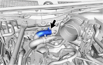
DISCONNECT OUTLET HEATER WATER HOSE
-
Slide the clamp and disconnect the outlet heater water hose from the No. 2 water by-pass pipe assembly.
Note
Do not apply excessive force to the heater water hose outlet.
-
-
DISCONNECT WATER HOSE SUB-ASSEMBLY
-
for 2WD:
-
for AWD:
-
-
DISCONNECT NO. 2 OIL COOLER OUTLET HOSE
-
DISCONNECT TRANSMISSION OIL COOLER HOSE
-
DISCONNECT DISCHARGE HOSE SUB-ASSEMBLY
-
for 2WD:
-
for AWD:
-
-
DISCONNECT SUCTION HOSE SUB-ASSEMBLY A
-
for 2WD:
-
for AWD:
-
-
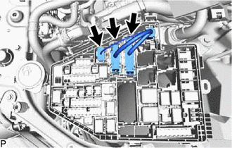
REMOVE NO. 2 RELAY BLOCK COVER
-
Detach the 4 claws and remove the No. 2 relay block cover.
-
-
REMOVE ECM
-
DISCONNECT ENGINE WIRE
-
Disconnect the 3 connectors.
-
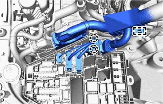
Detach the clamp and 2 claws and disconnect the engine wire from the relay block.
-
-
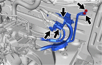
DISCONNECT NO. 3 ENGINE ROOM WIRE
-
Remove the 2 bolts of the No. 3 engine room wire.
-
Disconnect the 2 connectors and No. 3 engine room wire.
-
Disconnect the connector and air conditioning wire.
-
-
DISCONNECT NO. 3 ENGINE WIRE
-
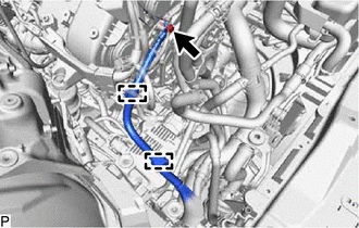
Remove the bolt, 2 clamps and disconnect the No. 3 engine wire.
-
-
DISCONNECT FUEL TUBE SUB-ASSEMBLY
-
Detach the clamp and disconnect the fuel tube sub-assembly from the fuel main tube connector.
-
-
DISCONNECT NO. 2 FUEL TUBE SUB-ASSEMBLY
-
Detach the clamp and disconnect the No. 2 fuel tube sub-assembly from the fuel pipe.
-
-
REMOVE FRONT BUMPER COVER
-
for Sport Package:
-
except Sport Package:
-
-
REMOVE RADIATOR SUPPORT EXTENSION LH
-
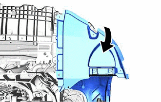
Open a part of the front fender liner LH as shown in the illustration.
-
Remove the 3 screws, detach the 2 claws and remove the radiator support extension LH from the radiator support opening cover.
-
-
REMOVE RADIATOR SUPPORT EXTENSION RH
-
Open a part of the front fender liner RH as shown in the illustration.
-
Remove the 3 screws, detach the 2 claws and remove the radiator support extension RH from the radiator support opening cover.
-
-
REMOVE RADIATOR SUPPORT OPENING COVER
-
Remove the 4 screws, detach the 3 claws and remove the radiator support opening cover from the front crossmember sub-assembly.
-
-
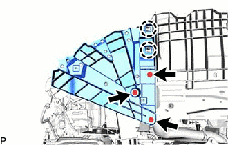
REMOVE NO. 2 FRONT BUMPER REINFORCEMENT SUB-ASSEMBLY
-
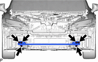
Remove the 6 nuts and No. 2 front bumper reinforcement sub-assembly.
-
-
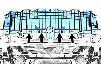
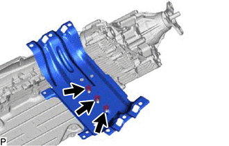
REMOVE REAR FRAME RAIL SUB-ASSEMBLY
-
for 2WD:
-
Remove the 6 bolts, 4 nuts and rear frame rail sub-assembly.
-
-
for AWD:
-
Remove the 6 bolts and rear frame rail sub-assembly.
-
-
-
REMOVE REAR FLOOR SIDE MEMBER COVER LH
-
REMOVE REAR FLOOR SIDE MEMBER COVER RH
-
REMOVE NO. 2 FLOOR BOARD SUB-ASSEMBLY
-
REMOVE FLOOR BOARD SUB-ASSEMBLY
-
REMOVE FRONT CENTER FLOOR BRACE SUB-ASSEMBLY
-
REMOVE FRONT EXHAUST PIPE ASSEMBLY
-
REMOVE NO. 1 CENTER FLOOR HEAT INSULATOR SUB-ASSEMBLY
-
REMOVE NO. 2 FUEL TANK PROTECTOR
-
REMOVE PROPELLER WITH CENTER BEARING SHAFT ASSEMBLY
-
DISCONNECT STEERING SLIDING WITH SHAFT YOKE SUB-ASSEMBLY (for 2WD)
-
DISCONNECT NO. 2 STEERING INTERMEDIATE SHAFT ASSEMBLY (for AWD)
-
DISCONNECT FRONT SKID CONTROL SENSOR WIRE LH (for 2WD)
-
DISCONNECT FRONT SKID CONTROL SENSOR WIRE RH (for 2WD)
Tech Tips
Remove the RH side following the same procedure as for the LH side.
-
DISCONNECT FRONT SPEED SENSOR LH (for AWD)
-
DISCONNECT FRONT SPEED SENSOR RH (for AWD)
Tech Tips
Remove the RH side following the same procedure as for the LH side.
-
REMOVE FRONT AXLE SHAFT NUT LH (for AWD)
-
REMOVE FRONT AXLE SHAFT NUT RH (for AWD)
Tech Tips
Remove the RH side following the same procedure as for the LH side.
-
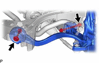
REMOVE FRONT HEIGHT CONTROL SENSOR SUB-ASSEMBLY LH
-
for 2WD:
-
for AWD:
-
-
REMOVE FRONT HEIGHT CONTROL SENSOR SUB-ASSEMBLY RH
Tech Tips
Remove the RH side following the same procedure as for the LH side.
-
DISCONNECT FRONT DISC BRAKE CYLINDER ASSEMBLY LH
-
for 2WD:
-
for AWD:
-
-
DISCONNECT FRONT DISC BRAKE CYLINDER ASSEMBLY RH
Tech Tips
Remove the RH side following the same procedure as for the LH side.
-
REMOVE FRONT DISC LH
-
REMOVE FRONT DISC RH
Tech Tips
Remove the RH side following the same procedure as for the LH side.
-
REMOVE FRONT DISC BRAKE DUST COVER LH
-
REMOVE FRONT DISC BRAKE DUST COVER RH
Tech Tips
Remove the RH side following the same procedure as for the LH side.
-
DISCONNECT TIE ROD ASSEMBLY LH
-
for 2WD:
-
for AWD:
-
-
DISCONNECT TIE ROD ASSEMBLY RH
Tech Tips
Remove the RH side following the same procedure as for the LH side.
-
DISCONNECT FRONT STABILIZER LINK ASSEMBLY LH (for 2WD)
-
DISCONNECT FRONT STABILIZER LINK ASSEMBLY RH (for 2WD)
Tech Tips
Remove the RH side following the same procedure as for the LH side.
-
DISCONNECT FRONT SHOCK ABSORBER ASSEMBLY LH (for 2WD)
-
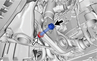
Bolt Nut Remove the bolt and nut, and separate the front shock absorber assembly LH from the lower No. 2 suspension arm assembly LH.
Note
Because the nut has its own stopper, do not turn the nut. Loosen the bolt with the nut secured.
-
-
DISCONNECT FRONT SHOCK ABSORBER ASSEMBLY RH (for 2WD)
Tech Tips
Remove the RH side following the same procedure as for the LH side.
-
DISCONNECT FRONT SHOCK ABSORBER ASSEMBLY LH (for AWD)
-
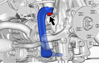
Remove the bolt. Then disconnect the absorber and absorber bracket.
-
-
DISCONNECT FRONT SHOCK ABSORBER ASSEMBLY RH (for AWD)
Tech Tips
Remove the RH side following the same procedure as for the LH side.
-
DISCONNECT STEERING KNUCKLE LH
-
for 2WD:
-
for AWD:
-
-
DISCONNECT STEERING KNUCKLE RH
Tech Tips
Remove the RH side following the same procedure as for the LH side.
-
REMOVE STEERING KNUCKLE LH (for 2WD)
-
Remove the 2 bolts, 2 nuts and steering knuckle LH.
-
-
REMOVE STEERING KNUCKLE RH (for 2WD)
Tech Tips
Remove the RH side following the same procedure as for the LH side.
-
REMOVE STEERING KNUCKLE LH (for AWD)
-
REMOVE STEERING KNUCKLE RH (for AWD)
Tech Tips
Remove the RH side following the same procedure as for the LH side.
-
REMOVE ENGINE SIDE COVER LH (for 2WD)
-
REMOVE ENGINE SIDE COVER RH (for 2WD)
Tech Tips
Remove the RH side following the same procedure as for the LH side.
-
REMOVE REAR LOWER ARM MOUNTING REINFORCEMENT SUB-ASSEMBLY LH (for 2WD)
-
REMOVE REAR LOWER ARM MOUNTING REINFORCEMENT SUB-ASSEMBLY RH (for 2WD)
Tech Tips
Remove the RH side following the same procedure as for the LH side.
-
INSTALL ENGINE HANGER
-

*a No. 1 engine hanger *b No. 2 engine hanger Install the No. 1 engine hanger and No. 2 engine hanger with the 4 bolts as shown in the illustration.
- Torque:
- 33 N*m { 337 kgf*cm, 24 ft.*lbf }
Tech Tips
No. 1 Engine Hanger 12281 - 31070 No. 2 Engine Hanger 12282 - 31160 Bolt 91671 - 10825
-
-
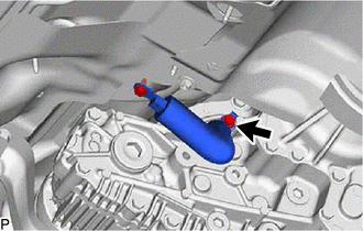
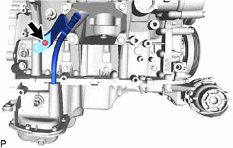
DISCONNECT NO. 2 PARKING LOCK RELEASE CABLE ASSEMBLY
-
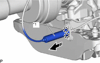
*1 Cover 
Disconnect Detach the 2 claws and disconnect the cover from the No. 2 parking lock release cable assembly as shown in the illustration.
-
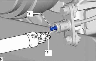
*1 Parking Lock Release Lever Assembly Cable End *2 No. 2 Parking Lock Release Cable Assembly Cable End Disconnect the parking lock release lever assembly cable end from the No. 2 parking lock release cable assembly cable end.
-
-
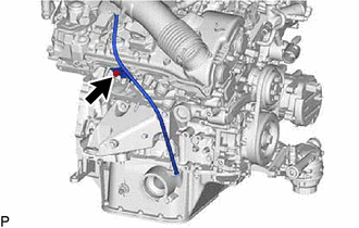
DISCONNECT NO. 2 GROUND WIRE
-
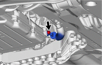
for 2WD:
-
Remove the bolt and disconnect the No. 2 ground wire.
-
-
for AWD:
-
Remove the bolt and disconnect the No. 2 ground wire.
-
-
-
REMOVE ENGINE AND TRANSMISSION ASSEMBLY (for 2WD)
-

Place Wooden Block or Plate Attachments Set the engine on an engine lifter.
Note
-
Place wooden blocks or plate lift attachments so that the engine is level.
-
With the exception of installing the engine assembly to an engine stand or removing the engine assembly from an engine stand, do not perform any work on the engine while it is suspended, as doing so is dangerous.
-
Never install attachments to the oil pan of the engine assembly or transmission as doing so may deform the oil pan.
-
-
Remove the 6 bolts, and then separate the rear engine mounting member.
-
Bolt Nut Remove the 2 bolts and 2 nuts shown in the illustration.
-
Operate the engine lifter, then slowly remove the engine and transmission assembly from the vehicle.
Note
-
Make sure the engine is clear of all wiring and hoses.
-
While lowering the engine from the vehicle, do not allow it to contact the vehicle.
-
-
Attach an engine sling device and hang the engine with a chain block.
Note
Pay attention to the angle of the sling device as the engine assembly or engine hangers may be damaged or deformed if the angle is incorrect.
-
-
REMOVE ENGINE AND TRANSMISSION ASSEMBLY (for AWD)
-
Place Wooden Block or Plate Attachments Set the engine on an engine lifter.
Note
-
Place wooden blocks or plate lift attachments so that the engine is level.
-
With the exception of installing the engine assembly to an engine stand or removing the engine assembly from an engine stand, do not perform any work on the engine while it is suspended, as doing so is dangerous.
-
Never install attachments to the oil pan of the engine assembly or transmission as doing so may deform the oil pan.
-
-
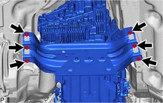
Remove the 6 bolts, and then separate the rear engine mounting member.
-

Bolt Nut Remove the 2 bolts and 2 nuts shown in the illustration.
-
Operate the engine lifter, then slowly remove the engine and transmission assembly from the vehicle.
Note
-
Make sure the engine is clear of all wiring and hoses.
-
While lowering the engine from the vehicle, do not allow it to contact the vehicle.
-
-
Attach an engine sling device and hang the engine with a chain block.
Note
Pay attention to the angle of the sling device as the engine assembly or engine hangers may be damaged or deformed if the angle is incorrect.
-
-
REMOVE NO. 2 ENGINE OIL LEVEL DIPSTICK GUIDE (for 2WD)
-
REMOVE ENGINE OIL LEVEL DIPSTICK GUIDE
-
for 2WD:
-
Remove the bolt, then remove the engine oil level dipstick guide.
-
-
for AWD:
-
Remove the bolt, then remove the engine oil level dipstick guide.
-
-
Remove the O-ring from the engine oil level dipstick guide.
-
-
REMOVE NO. 1 EGR PIPE
-
DISCONNECT AIR FUEL RATIO SENSOR
-
REMOVE EXHAUST MANIFOLD ASSEMBLY LH (for 2WD)
-
REMOVE EXHAUST MANIFOLD ASSEMBLY RH (for 2WD)
-
REMOVE EXHAUST MANIFOLD ASSEMBLY LH (for AWD)
-
REMOVE EXHAUST MANIFOLD ASSEMBLY RH (for AWD)
-
REMOVE FRONT PROPELLER SHAFT ASSEMBLY (for AWD)
-
REMOVE FLYWHEEL HOUSING SIDE COVER
-
for 2WD:
-
for AWD:
-
-
REMOVE HYBRID VEHICLE TRANSMISSION ASSEMBLY
-
for 2WD:
-
for AWD:
-
-
REMOVE TRANSMISSION INPUT DAMPER COVER ASSEMBLY
-
REMOVE FLYWHEEL SUB-ASSEMBLY
-
REMOVE FRONT DRIVE SHAFT ASSEMBLY LH (for AWD)
-
REMOVE FRONT DRIVE SHAFT ASSEMBLY RH (for AWD)
-
REMOVE FRONT DIFFERENTIAL CARRIER ASSEMBLY (for AWD)
-
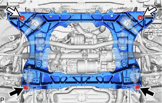
DISCONNECT FRONT FRAME CROSSMEMBER SUB-ASSEMBLY (for 2WD)
-
*a LH Side *b RH Side Remove the 2 bolts, then disconnect the front suspension crossmember sub-assembly from the engine.
-
-
DISCONNECT FRONT FRAME ASSEMBLY (for AWD)
-
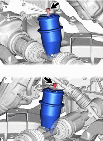
*a LH Side *b RH Side Remove the 2 bolts, then disconnect the front suspension crossmember sub-assembly from the engine.
-
-
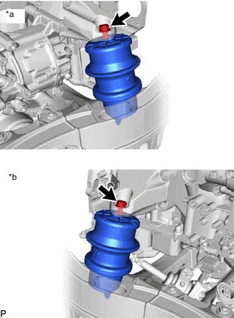
REMOVE FRONT ENGINE MOUNTING INSULATOR
Tech Tips
Only perform this procedure when replacement of the engine mounting insulator is necessary.
-
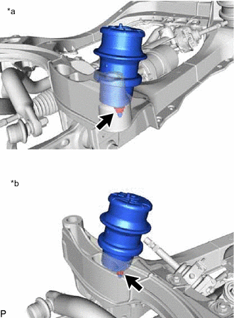
*a LH Side *b RH Side for 2WD:
-
Remove the 2 nuts and front engine mounting insulator RH and LH.
-
-
*a LH Side *b RH Side for AWD:
-
Remove the 4 nuts and front engine mounting insulator RH and LH.
-
-
-
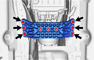
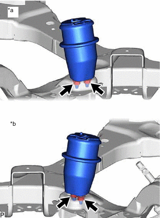
REMOVE REAR ENGINE MOUNTING MEMBER
-
for 2WD:
-
Remove the 3 nuts and rear engine mounting member from the rear engine mounting insulator.
-
-
for AWD:
-
Remove the 3 nuts and rear engine mounting member from the rear engine mounting insulator.
-
-
-
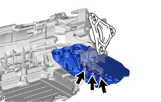
REMOVE REAR ENGINE MOUNTING INSULATOR
-
for 2WD:
-
for AWD:
-
-
INSTALL ENGINE ON ENGINE STAND
-
Install the engine to an engine stand with bolts.
Note
-
Pay attention to the angle of the sling device as the engine assembly or engine hangers may be damaged or deformed if the angle is incorrect.
-
With the exception of installing the engine assembly to an engine stand or removing the engine assembly from an engine stand, do not perform any work on the engine while it is suspended, as doing so is dangerous.
-
-
Remove the 4 bolts and 2 engine hangers.
-