REPAIR INSTRUCTION PRECAUTION
-
BASIC REPAIR HINT
-
HINTS ON OPERATIONS
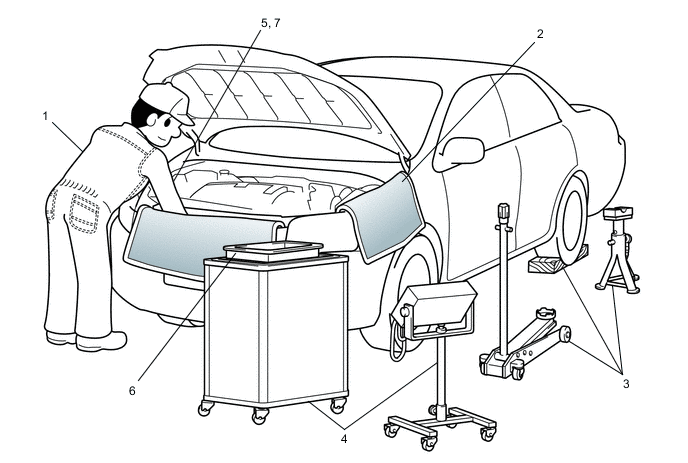
1 Attire
-
Always wear a clean uniform.
-
A hat and safety shoes must be worn.
2 Vehicle protection Prepare a grille cover, fender cover, seat cover and floor mat before starting work. 3 Safety procedures
-
When working with 2 or more persons, be sure to check the safety of one another.
-
When working with the engine running, make sure to provide ventilation for exhaust fumes in the workshop.
-
If working on high temperature, high pressure, rotating, moving or vibrating parts, wear appropriate safety equipment and take extra care not to injure yourself or others.
-
When jacking up the vehicle, be sure to support the vehicle at the specified locations with safety stands.
-
When lifting up the vehicle, use appropriate safety equipment.
4 Preparation of tools and measuring equipment Before starting work, prepare a tool stand, SST, measuring equipment, oil, and any replacement parts required. 5 Removal and installation, disassembly and assembly operations
-
Diagnose with a thorough understanding of proper procedures and of the reported problem.
-
Before removing any parts, check the general condition of the assembly and for deformation and damage.
-
If the procedure is complicated, take notes. For example, note the total number of electrical connections, bolts or hoses removed. Add matchmarks to ensure reassembly of components in the original positions. Temporarily mark hoses and their fittings if needed.
-
Clean and wash the removed parts if necessary and assemble them after a thorough check.
6 Removed parts
-
Place the removed parts in a separate box to avoid mixing them up with new parts or contaminating the new parts.
-
For non-reusable parts such as gaskets, O-rings and self-locking nuts, replace them with new ones as instructed in this manual.
-
Retain the removed parts for customer inspection, if requested.
7* Checks to perform after work is finished
-
Make sure that removed and installed parts (oil filler cap, level dipstick, floor mat, etc.) are properly installed/tightened.
-
Make sure that none of the cloths or tools that were used have been left in the engine compartment or within the vehicle.
-
Check that there are no oil leaks.
CAUTION:
*: Be sure to perform these checks properly, not performing these checks properly after finishing work can lead to a serious accident or injury.
-
-
JACKING UP AND SUPPORTING THE VEHICLE
-
Care must be taken when jacking up and supporting the vehicle. Be sure to lift and support the vehicle at the proper locations.
-
-
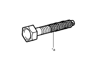
*a Seal Lock Adhesive PRECOATED PARTS
-
Precoated parts are bolts and nuts that are coated with seal lock adhesive at the factory.
-
If a precoated part is retightened, loosened or moved in any way, it must be recoated with the specified adhesive.
-
When reusing a precoated part, clean off the old adhesive and dry the part with compressed air. Then apply new seal lock adhesive appropriately to that part.
-
Some seal lock agents harden slowly. You may have to wait for the seal lock adhesive to harden.
-
-
GASKETS
-
When necessary, use a sealer on gaskets to prevent leaks.
-
-
BOLTS, NUTS AND SCREWS
-
Carefully follow all of the specifications for tightening torque. Always use a torque wrench.
-
Make sure that no foreign matter (burrs, paint, etc.) gets trapped under the heads of the bolts and nuts when tightening them.
-
-
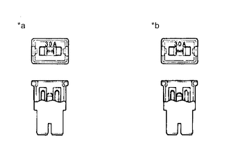
*a NG *b OK FUSES
-
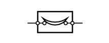
When inspecting a fuse, check that the wire of the fuse is not broken.
-
If the wire of a fuse is broken, confirm that there are no shorts in its circuit.
-
When a fuse is replaced, a fuse with the same amperage rating must be used.
Illustration Symbol Part Name Abbreviation 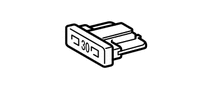
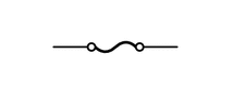
FUSE FUSE 
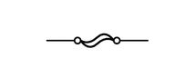
MEDIUM CURRENT FUSE M-FUSE 
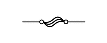
HIGH CURRENT FUSE H-FUSE 
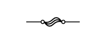
FUSIBLE LINK FL 
CIRCUIT BREAKER CB 
FUSIBLE LINK FL
-
-
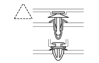
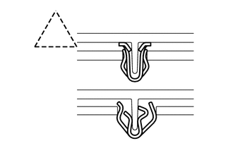
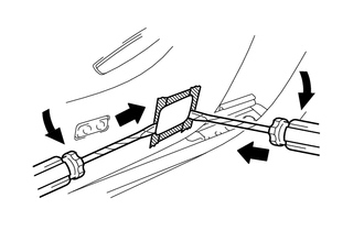
CLIPS
-
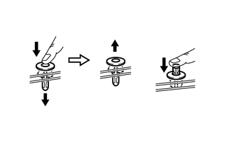
The removal and installation methods of typical clips used for vehicle body parts are shown in the table below.
Tech Tips
If clips are damaged during a procedure, always replace the damaged clips with new ones.
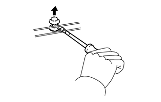
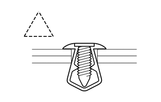
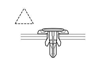
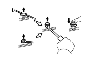
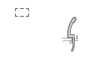
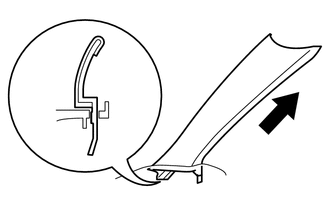
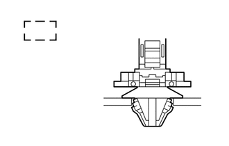
Shape (Example) Removal/Installation 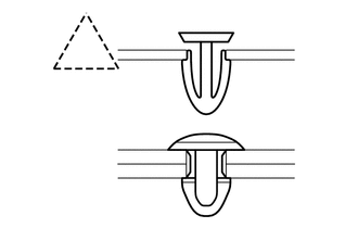
Remove the clips with a clip remover or pliers.
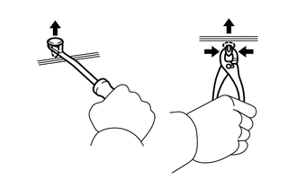
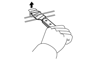
Remove the clips using a clip remover or a screwdriver with its tip wrapped with protective tape.
Remove the clips with a wide scraper to prevent panel damage.
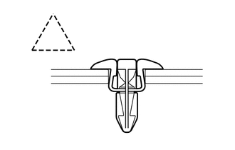
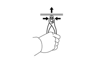
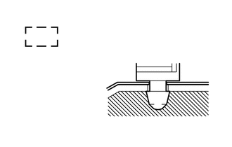
Remove the clips by pushing the center pin through and pulling out the shell.
Remove the clips by unscrewing the center pin and prying out the shell.
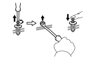
Remove the clips by prying out the pin using a screwdriver with its tip wrapped with protective tape and then prying out the shell.
-
-
CLAWS
-
The removal and installation methods of typical claws used for vehicle body parts are shown in the table below.
Tech Tips
If claws are damaged during a procedure, always replace the cap or cover that has damaged claws with a new one.
Shape (Example) Illustration / Procedures 
Disengage the claws using a screwdriver with its tip wrapped with protective tape to remove the caps or covers.
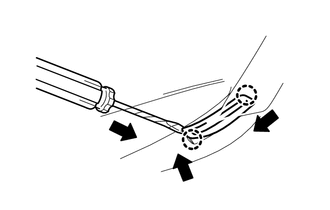
Disengage the claws using a screwdriver with its tip wrapped with protective tape to remove the caps or covers.
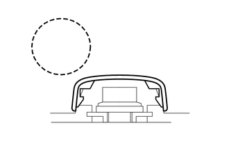
Disengage the claws using a screwdriver with its tip wrapped with protective tape to remove the caps or covers.
-
-
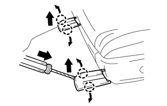
HINGES, GUIDES, CLAMPS, PINS, ETC.
-
The removal and installation methods of typical hinges, guides, clamps and pins used for vehicle body parts are shown in the table below.
Tech Tips
If clamps are damaged during a procedure, always replace the cap or cover that has damaged clamps with a new one.
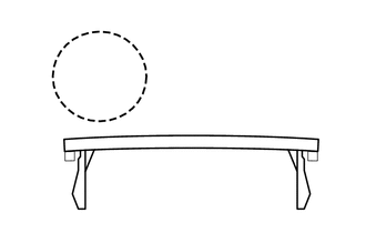
Shape (Example) Removal/Installation 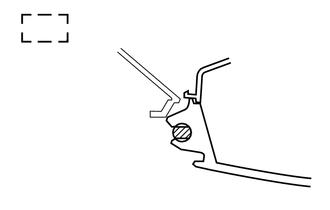
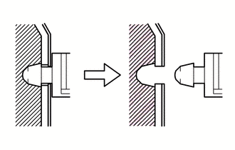
Pull away from the pins to disengage.
Disengage the pins by pulling.
Remove the clamps with pliers.
Disengage the pins by pulling.
-
-
REMOVAL AND INSTALLATION OF VACUUM HOSES
-
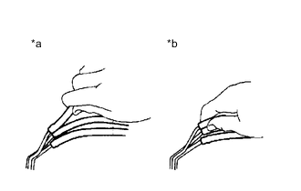
*a Incorrect *b Correct To disconnect a vacuum hose, pull and twist it from the end of the hose. Do not pull it from the middle of the hose as this may damage the hose.
-
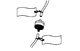
When disconnecting vacuum hoses, use tags to identify where they should be reconnected.
-
After completing any hose related repairs, double-check that the vacuum hoses are properly connected. The label under the hood shows the proper layout.
-
When using a vacuum gauge, never force the hose onto a connector that is too large. If a hose has been stretched, air may leak. Use a step-down adapter if necessary.
-
-
TORQUE WHEN USING TORQUE WRENCH WITH EXTENSION TOOL
-
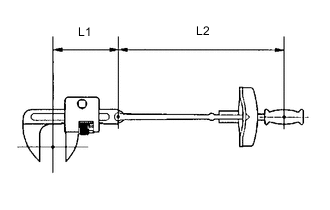
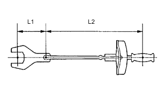
Use the formula below to calculate special torque values for situations where SST or an extension tool is combined with a torque wrench.
T' Reading of torque wrench (N*m (kgf*cm, ft.*lbf)) T Torque (N*m (kgf*cm, ft.*lbf)) L1 Length of SST or extension tool (cm (in.)) L2 Length of torque wrench (cm (in.)) Note
If an extension tool or SST is combined with a torque wrench and used to tighten to a torque specification in this manual, the actual torque will be excessive and parts will be damaged.
-
-
-
PRECAUTIONS FOR HIGH-VOLTAGE CIRCUIT INSPECTION AND SERVICE
CAUTION:
-
This vehicle has a hybrid system that operates at voltages of up to 650 V. An organic electrolyte containing carbonic acid esters as its main component is used as the electrolyte for the HV battery. Be sure to follow the instructions in this manual to handle the system correctly. Failure to do so may result in serious injury or electrocution.
-
Technicians must undergo special training to be able to service and inspect the high-voltage system.
-
All high-voltage wire harnesses and connectors are colored orange. The HV battery and other high-voltage components have "High Voltage" caution labels. Do not carelessly touch these wires or components.
-
When there is a problem with a wire harness or connector of a high-voltage circuit, repairs to the harness or connector should not be attempted. Replace damaged or malfunctioning high-voltage wire or connector.
-
Before inspecting or servicing the high-voltage system, be sure to follow all safety measures, such as wearing insulated gloves and removing the service plug grip to prevent electrocution. Carry the removed service plug grip in your pocket to prevent other technicians from accidentally reconnecting it while you are servicing the vehicle.
Note
After removing the service plug grip, turning the power switch on (READY) may cause a malfunction. Do not turn the power switch on (READY) unless instructed by the repair manual.
-
After removing the service plug grip, wait 10 minutes before touching any of the high-voltage connectors and terminals.
Tech Tips
Waiting for at least 10 minutes is required to discharge the high voltage capacitor inside the inverter with converter assembly.
-
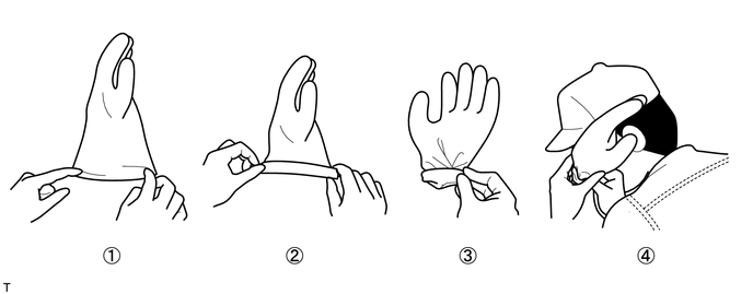
Before using insulated gloves, be sure to check them for cracks, tears and other types of damage by performing the following procedure.
-
Place the glove on its side.
-
Roll the opening up 2 or 3 times.
-
Fold the opening in half to close it.
-
Confirm that there are no air leaks.
-
-
When servicing the vehicle, do not carry metal objects like mechanical pencils or rulers that can be dropped accidentally and cause a short circuit.
-
Before touching a bare high-voltage terminal, wear insulated gloves and use a tester to make sure that the terminal voltage is 0 V.
-
After disconnecting or exposing a high-voltage connector or terminal, insulate it immediately using insulating tape.
-
Bolts and nuts for high-voltage terminals should be tightened to the specified torque. Both insufficient and excessive torque can cause a malfunction.
-
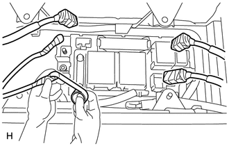
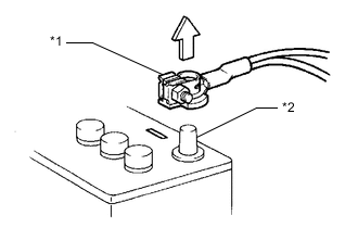
Use the "CAUTION: HIGH VOLTAGE DO NOT TOUCH" sign to notify other technicians that the high-voltage system is being inspected and/or repaired.
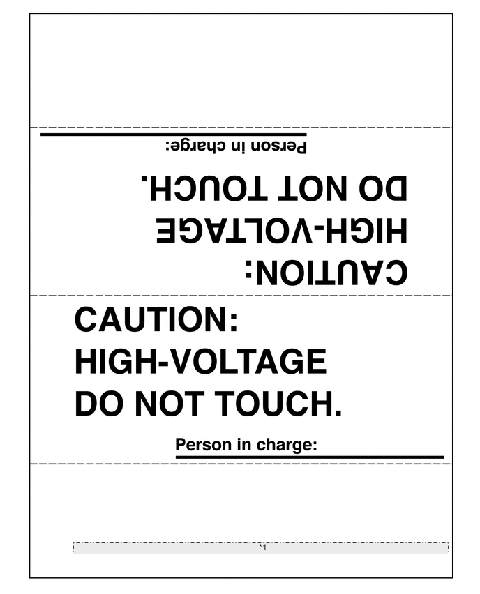
*1 When performing work on the HV system, fold this sign and put it on the roof of the vehicle. -
After servicing the high-voltage system and before reinstalling the service plug grip, check again that you have not left any parts or tools inside, that the high-voltage terminals are firmly tightened, and that the connectors are correctly connected.
-
When performing work involving a high-voltage circuit, use either a tool wrapped with vinyl insulation tape or an insulated tool.
-
When installing hybrid system components such as the HV battery, make sure that the polarity of all connections is correct.
-
-
PRECAUTIONS TO BE OBSERVED WHEN INSPECTING OR SERVICING ENGINE COMPARTMENT
-
The vehicle automatically turns the engine on and off when the READY light on the combination meter assembly is illuminated. To avoid injury, make sure that both the indicator on the power switch and the READY light on the combination meter assembly are off.
-
-
ACTIONS TO BE TAKEN WHEN A WARNING LIGHT IS ILLUMINATED
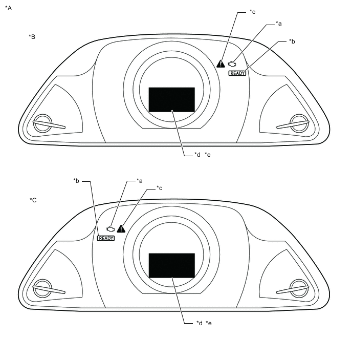
*A except Sport Package *B for LHD *C for RHD - - *a MIL *b READY Light *c Master Warning Light *d Charge Warning *e Multi-information Display - - 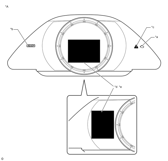
*A for Sport Package - - *a MIL *b READY Light *c Master Warning Light *d Charge Warning *e Multi-information Display - -
-
If one of the warning lights (2) to (4) illuminates, connect the GTS to the DLC3 to check the DTCs (Diagnostic Trouble Codes). Then, refer to the applicable troubleshooting steps in this manual to inspect and repair the affected area. The foregoing actions are also required if the READY light does not illuminate when attempting to turn the power switch on (READY).
Indicator Light Vehicle Condition (1) READY Light (To Drive) Illuminates when the power switch is turned on (READY), indicating that the vehicle is ready to be driven. (2) Master Warning Light Depending on the warning, the master warning light illuminates or flashes to indicate that a warning is currently being displayed on the multi-information display. Depending on the warning, the buzzer may also sound.
When any malfunction occurs in the hybrid control system or hybrid battery system, the master warning light illuminates or flashes along with a buzzer, and a warning, such as, "Hybrid System Malfunction", is displayed on the multi-information display.
(3) MIL Illuminates when there is a malfunction in the engine control system. (4) Charge Warning Displayed when there is a malfunction in the charging system.
(Be sure to check for DTCs (Diagnostic Trouble Codes) if this light illuminates together with the master warning light.)
-
-
ACTIONS TO BE TAKEN WHEN BATTERIES ARE DISCHARGED
Tech Tips
The vehicle uses a 12 V auxiliary and a 310.8 V HV battery. Therefore, there are 2 recharging methods when the batteries are discharged.
-
Perform this procedure when the auxiliary battery is fully discharged.
Tech Tips
The following problems indicate that the auxiliary battery is discharged:
-
No display appears on the instrument panel when the power switch is turned on (IG).
-
The hybrid system does not start.
-
The headlights are dim.
-
The sound from the horn is weak.
Note
Never use a quick charger.
Tech Tips
The booster terminal cannot be used to rescue a vehicle with a discharged battery.
-
Engage the parking brake.
-
Turn the power switch off and remove the key from the interior detection area.
-
for LHD:
Remove the radiator cover plate.
-
for RHD
Remove the upper radiator support seal.
-
Remove the No. 2 engine room relay block cover.
-
Using booster cables, connect the 12 V auxiliary battery of the rescue vehicle to the auxiliary battery of the stalled vehicle as shown in the illustration.
Connecting Sequence Connecting Location 1 Positive booster terminal of stalled vehicle 2 Positive (+) auxiliary battery terminal of rescue vehicle 3 Negative (-) auxiliary battery terminal of rescue vehicle 4 Position shown in the illustration on stalled vehicle 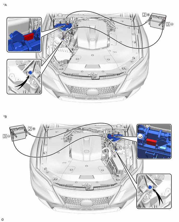
*A for LHD *B for RHD -
Start the engine of the rescue vehicle and run the engine at a speed slightly higher than usual.
-
Turn the power switch on (READY).
Note
Immediately disconnect the booster cables in the reverse order of connection after the hybrid system has started. Do not leave the booster cables connected because they are not designed for recharging purposes.
If the hybrid system fails to start and "Traction Battery needs to be Protected Shift into [P] to Restart" or "Traction Battery Needs to be Protected Refrain from the Use of [N] Position" is displayed on the multi-information display, the HV battery may be discharged.
-
-
When the HV battery is discharged:
-
Using the THS charger, charge the HV battery.
Tech Tips
Perform this operation when the HV battery is discharged or low, or if a low traction battery warning message is displayed on the multi-information display and DTC P300000 or P300016 is stored in the battery ECU assembly.
-
-
-
ACTIONS TO BE TAKEN FOR VEHICLES DAMAGED BY IMPACT
CAUTION:
This vehicle has a hybrid system that operates at voltages of up to 650 V. An organic electrolyte containing carbonic acid esters as its main component is used as the electrolyte for the HV battery. Be sure to follow the instructions in this manual to handle the system correctly. Failure to do so may result in serious injury or electrocution.
-
Items to be prepared for the accident site
-
Protective clothing (insulated gloves, rubber gloves, goggles, organic solvent mask, safety shoes and solvent resistant apron (for organic solvent))
-
Soap
-
ABC fire extinguisher (effective against both oil flames and electrical flames)
-
A shop rag or piece of cloth (for wiping up electrolyte)
-
Insulating tape (for insulating cables)
-
Electrical tester
-
-
Actions to be taken at the accident site
CAUTION:
-
Do not touch any bare cables that could be high-voltage cables. If a cable must be touched or if accidental contact is possible, wear insulated gloves and insulate the cable using insulating tape.
-
If the vehicle catches on fire, use an ABC fire extinguisher to extinguish the fire. Trying to extinguish a fire using only a small amount of water can be more dangerous than effective. Use a substantial amount of water or wait for firefighters.
-
Visually check the HV battery and surrounding area for any electrolyte leakage. Do not touch any leaked liquid because it could be organic electrolyte that contains carbonic acid esters.
-
The electrolyte is flammable. Keep all ignition sources such as open flame and hot objects away from the electrolyte.
-
Electrolyte leaks may cause acute poisoning if a high concentration of the vapor from the electrolyte is inhaled. In case of inhalation, move the affected person to a place with ample fresh air and let them lie quietly. Seek medical care.
-
If the vehicle is submerged in water, do not touch any of the high-voltage components or cables including the service plug grip, as doing so poses an electrocution hazard. Work on the vehicle only after the vehicle has been pulled out of the water.
-
If the electrolyte comes in contact with your skin, wash the area thoroughly with soap and plenty of water, and seek medical care. If the electrolyte comes in contact with an article of clothing, take it off immediately. Prolonged contact with the electrolyte may cause skin irritation.
-
If the electrolyte comes in contact with your eyes, call out loudly for help. Do not rub your eyes. Immediately flush them with a large amount of water for at least 15 minutes and seek medical care.
-
If electrolyte is swallowed, seek medical care immediately. Do not induce vomiting, unless instructed by the doctor.
-
Check the vicinity of the HV battery for any leakage of the electrolyte.
CAUTION:
Do not touch any leaked liquid because it could be the organic electrolyte that contains carbonic acid esters. If contact is unavoidable, wipe up the liquid using a cloth while wearing rubber gloves, goggles and an organic solvent mask. Do not leave electrolyte-contaminated cloths unattended. Place contaminated cloths in an appropriate airtight container and dispose of them according to local regulations.
-
If damage to any of the high-voltage components or cables is suspected, cut the high-voltage circuit using the following procedure.
CAUTION:
Be sure to wear insulated gloves, goggles and safety shoes.
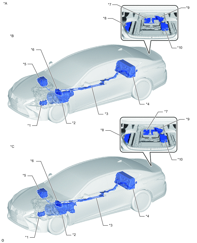
*A for LHD *B for 2WD *C for AWD - - *1 Compressor with Motor Assembly *2 Hybrid Vehicle Transmission Assembly *3 HV Floor Under Wire *4 HV Battery *5 Inverter with Converter Assembly *6 No. 2 Engine Room Relay Block *7 Auxiliary Battery *8 No. 2 Luggage Room Relay Block *9 No. 1 Luggage Room Relay Block *10 Sub-Battery with Control Assembly 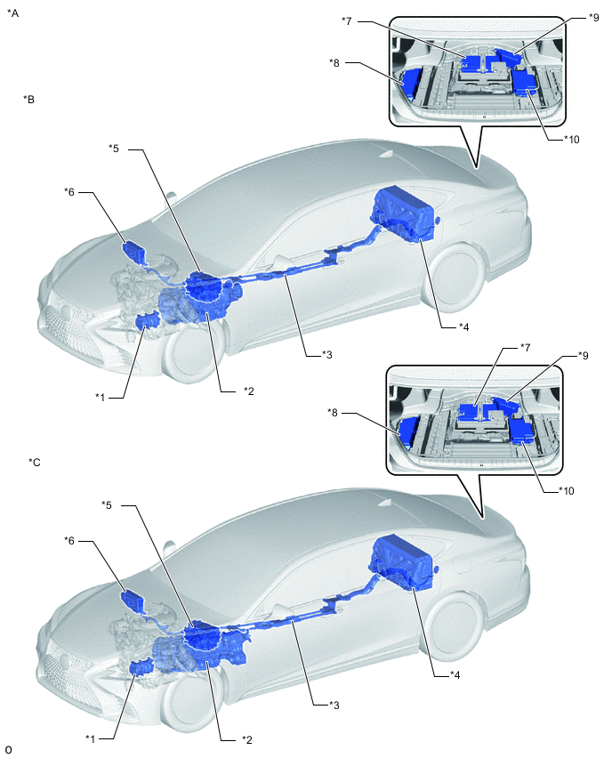
*A for RHD *B for 2WD *C for AWD - - *1 Compressor with Motor Assembly *2 Hybrid Vehicle Transmission Assembly *3 HV Floor Under Wire *4 HV Battery *5 Inverter with Converter Assembly *6 No. 2 Engine Room Relay Block *7 Auxiliary Battery *8 No. 2 Luggage Room Relay Block *9 No. 1 Luggage Room Relay Block *10 Sub-Battery with Control Assembly -
Turn the power switch off.
Tech Tips
If the power switch cannot be turned off, remove the IGCT No.1 fuse from the No. 2 luggage room relay block.
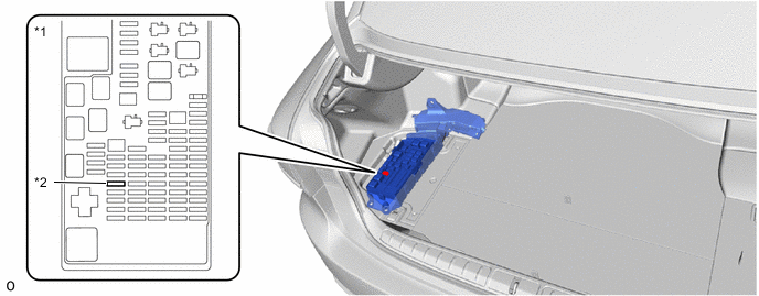
*1 No. 2 Luggage Room Relay Block *2 IGCT No.1 Fuse -
Disconnect the cable from the negative (-) auxiliary battery terminal.
-
While wearing insulated gloves, remove the service plug grip.
Note
After removing the service plug grip, turning the power switch on (READY) may cause a malfunction. Do not turn the power switch on (READY) unless instructed by the repair manual.
-
-
Moving the damaged vehicle
Note
When towing the vehicle, refer to the Precautions for Towing Front Wheel Drive Vehicles.
If any of the following conditions are met, tow the vehicle away using a tow truck.
-
One or more of the high-voltage components or cables are damaged.
-
Components related to driving, the hybrid transmission or the fuel system are damaged.
-
The master warning light is on.
-
The READY light does not come on when attempting to turn the power switch on (READY).
CAUTION:
Before towing the vehicle away using a tow truck, disconnect the cable from the negative (-) auxiliary battery terminal and remove the service plug grip.
Note
Perform the procedure below if the master warning light turns on, or there are abnormal noises, unusual smells, or strong vibrations while driving:
-
Park the vehicle in a safe place.
-
Apply the parking brake, push the P switch and confirm that park (P) has been selected.
-
Turn the power switch off, and disconnect the cable from the negative (-) auxiliary battery terminal.
-
While wearing insulated gloves, remove the service plug grip.
-
-
Actions required after moving the damaged vehicle
-
Procedure
If there is liquid on the floor, it could be organic electrolyte containing carbonic acid esters. Wipe up the liquid using a cloth while wearing rubber gloves, goggles and an organic solvent mask. Do not leave electrolyte-contaminated cloths unattended. Place contaminated cloths in an appropriate airtight container and dispose of them according to local regulations.
-
-
Items to be prepared (when repairing a damaged vehicle)
-
Protective clothing (insulated gloves, rubber gloves, goggles, organic solvent mask, safety shoes and solvent resistant apron (for organic solvent))
-
Soap
-
ABC fire extinguisher (effective against both oil flames and electrical flames)
-
A shop rag or piece of cloth (for wiping up electrolyte)
-
Insulating tape (for insulating cables)
-
Electrical tester
-
-
Precautions to be observed when servicing a damaged vehicle
CAUTION:
-
Always follow the instructions to ensure safety.
-
Do not touch any bare cables that could be high-voltage cables. If a cable must be touched or if accidental contact is possible, wear insulated gloves and insulate the cable using insulating tape.
-
Visually check the HV battery and surrounding area for any electrolyte leakage. Do not touch any leaked liquid because it could be organic electrolyte that contains carbonic acid esters.
-
The electrolyte is flammable. Keep all ignition sources such as open flame and hot objects away from the electrolyte.
-
Electrolyte leaks may cause acute poisoning if a high concentration of the vapor from the electrolyte is inhaled. In case of inhalation, move the affected person to a place with ample fresh air and let them lie quietly. Seek medical care.
-
If the electrolyte comes in contact with your skin, wash the area thoroughly with soap and plenty of water, and seek medical care. If the electrolyte comes in contact with an article of clothing, take it off immediately. Prolonged contact with the electrolyte may cause skin irritation.
-
If the electrolyte comes in contact with your eyes, call out loudly for help. Do not rub your eyes. Immediately flush them with a large amount of water for at least 15 minutes and seek medical care.
-
If electrolyte is swallowed, seek medical care immediately. Do not induce vomiting, unless instructed by the doctor.
-
Wear insulated or rubber gloves, goggles, and safety shoes.
-
Check the HV battery and surrounding area for any electrolyte leakage.
CAUTION:
Do not touch any leaked liquid because it could be the organic electrolyte that contains carbonic acid esters. If contact is unavoidable, wipe up the liquid using a cloth while wearing rubber gloves, goggles and an organic solvent mask. Do not leave electrolyte-contaminated cloths unattended. Place contaminated cloths in an appropriate airtight container and dispose of them according to local regulations.
-
Do not touch any bare cables that could be high-voltage cables. If a cable must be touched or if accidental contact is possible, perform the following: 1) wear insulated gloves and goggles, 2) measure the voltage between the cable and body ground using an electrical tester, and 3) insulate the cable using insulating tape.
-
If damage to any of the high-voltage components or cables is suspected, cut the high-voltage circuit using the following procedure.
CAUTION:
Do not touch any bare cables that could be high-voltage cables. If a cable must be touched or if accidental contact is possible, wear insulated gloves and insulate the cable using insulating tape.
-
Turn the power switch off.
Tech Tips
If the power switch cannot be turned off, remove the IGCT No.1 fuse from the No. 2 luggage room relay block.
*1 No. 2 Luggage Room Relay Block *2 IGCT No.1 Fuse -
Disconnect the cable from the negative (-) auxiliary battery terminal.
-
While wearing insulated gloves, remove the service plug grip.
Note
After removing the service plug grip, turning the power switch on (READY) may cause a malfunction. Do not turn the power switch on (READY) unless instructed by the repair manual.
-
-
Precautions to be taken when disposing of an HV battery
-
When disposing of an HV battery, make sure to return it through an authorized collection agent who is capable of handling it safely. If the HV battery is returned via the manufacturer specified route, it will be returned properly and in a safe manner by an authorized collection agent.
CAUTION:
-
Before returning the HV battery, make sure to perform a recovery inspection.
-
Accidents such as electric shock may result if the HV battery is disposed of improperly or abandoned. Therefore, make sure to return all HV batteries through an authorized collection agent.
-
To reduce the risk of fire, HV batteries must not be stored in an area where they will be exposed to fire or high temperatures.
-
If the temperature of the HV battery is high, leave it until the temperature drops.
-
-
-
Precautions to be observed when towing
-
Tow the damaged vehicle with its front and rear wheels lifted off the ground.
CAUTION:
Towing the damaged vehicle with its wheels on the ground will cause the motor to generate electricity. This electricity could, depending on the nature of the damage, leak and cause a fire.
-
-
Towing with all 4 wheels on the ground
CAUTION:
-
If the vehicle needs to be towed using a cable or chain with all 4 wheels on the ground, do not exceed 30 km/h (18 mph) and tow only for a short distance and then have the vehicle towed by a truck.
-
Turn the power switch on (IG), move the shift lever to N and confirm that neutral (N) has been selected.
-
Make sure not to turn the power switch off while the vehicle is being towed, as park (P) may be selected, which may result in damage or an accident.
-
If any abnormality in the damaged vehicle occurs during towing, stop towing immediately.
Tech Tips
Neutral (N) cannot be selected if the auxiliary battery is disconnected.
-
-
-
FOR VEHICLES EQUIPPED WITH SRS AIRBAG AND SEAT BELT PRETENSIONER
This vehicle is equipped with a Supplemental Restraint System (SRS).
CAUTION:
-
Before performing pre-disposal deployment of any SRS parts, review and closely follow all applicable environmental and hazardous material regulations. Pre-disposal deployment may be considered hazardous material treatment.
-
Failure to carry out the service operations in the correct sequence could cause the SRS to unexpectedly deploy during servicing and lead to a serious injury. Furthermore, if a mistake is made when servicing the SRS, it is possible that the SRS may fail to operate properly. Before servicing (including removal or installation of parts, inspection or replacement), be sure to read the following section carefully.
-
GENERAL NOTICE
-
As malfunctions of the SRS are difficult to confirm, Diagnostic Trouble Codes (DTCs) become the most important source of information when troubleshooting. When troubleshooting the SRS, always check for DTCs before disconnecting the auxiliary battery.
-
Work must be started at least 90 seconds after the power switch is turned off and the cable is disconnected from the negative (-) auxiliary battery terminal.
The SRS is equipped with a back-up power source. If work is started within 90 seconds of turning the power switch off and disconnecting the cable from the negative (-) auxiliary battery terminal, the SRS may deploy.
When the cable is disconnected from the negative (-) auxiliary battery terminal, the clock and audio system memory will be cleared. Before starting work, make a note of the settings of each memory system. When work is finished, reset the clock and audio system as before.
CAUTION:
Never use a back-up power source (auxiliary battery or other) to avoid clearing the system memory. The back-up power source may inadvertently power the SRS and cause it to deploy.
-
If the vehicle has been involved in a minor collision where the SRS does not deploy, the steering pad, front passenger airbag assembly, knee airbag assembly, seat side airbag assembly, rear seat cushion airbag assembly, curtain shield airbag assembly, seat outer belt assembly and pop up hood lifter assembly should be inspected before further use of the vehicle.
-
Never use SRS parts from another vehicle. When replacing parts, use new ones.
-
Before performing repairs, remove the airbag sensor assemblies if impacts are likely to be applied to the sensor during repairs.
-
Never disassemble and attempt to repair any of the airbag sensor assemblies or SRS parts.
-
Steering pad
-
Front passenger airbag assembly
-
Knee airbag assembly
-
Seat side airbag assembly
-
Rear seat cushion airbag assembly
-
Curtain shield airbag assembly
-
Seat outer belt assembly
-
Pop up hood lifter assembly
-
-
Replace any airbag sensor assembly or SRS parts if: 1) damage has occurred from being dropped, or 2) cracks, dents or other defects in the case, bracket or connector are present.
-
Do not directly expose the airbag sensor assemblies or SRS parts to hot air or flames.
-
Use a voltmeter/ohmmeter with high impedance (minimum = 10 kΩ) for troubleshooting electrical circuits.
-
Information labels are attached to the SRS parts. Follow the instructions on the labels.
-
After work on the SRS is completed, check the SRS warning light.
-
-
SPIRAL CABLE
-
The steering wheel must be fitted correctly to the steering column with the spiral cable at the neutral position. Otherwise, cable damage and other problems may occur. Refer to the information about correct installation of the steering wheel.
-
-
STEERING PAD
-
Always place a removed or new steering pad with the deployment surface facing upward. Placing the steering pad with the deployment surface facing downward could cause a serious accident if the airbag deploys. Also, do not place anything on top of the steering pad.
-
Never measure the resistance of the airbag squib. This may cause the airbag to deploy, which could cause serious injury.
-
Grease or detergents of any kind should not be applied to the steering pad.
-
Store the steering pad in an area where the ambient temperature is below 93°C (199°F), the humidity is not high and there is no electrical noise.
-
Before using an electric welder anywhere on the vehicle, disconnect the center airbag sensor assembly connectors. These connectors contain shorting springs. This feature reduces the possibility of the airbag deploying due to current entering the squib wiring.
-
When disposing of the vehicle or steering pad by itself, the airbag should be deployed using SST before disposal. Deploy the airbag in a safe place away from electrical noise.
-
-
FRONT PASSENGER AIRBAG ASSEMBLY
-
Always place a removed or new front passenger airbag assembly with the deployment surface facing upward. Placing the airbag assembly with the airbag deployment surface facing downward could cause a serious accident if the airbag deploys.
-
Never measure the resistance of the airbag squib. This may cause the airbag to deploy, which could cause serious injury.
-
Grease or detergents of any kind should not be applied to the front passenger airbag assembly.
-
Store the front passenger airbag assembly in an area where the ambient temperature is below 93°C (199°F), the humidity is not high and there is no electrical noise.
-
Before using an electric welder anywhere on the vehicle, disconnect the center airbag sensor assembly connectors. These connectors contain shorting springs. This feature reduces the possibility of the airbag deploying due to current entering the squib wiring.
-
When disposing of the vehicle or front passenger airbag assembly by itself, the airbag should be deployed using SST before disposal. Deploy the airbag in a safe place away from electrical noise.
-
-
KNEE AIRBAG ASSEMBLY
-
Always place a removed or new knee airbag assembly with the airbag deployment surface facing upward. Placing the airbag assembly with the airbag deployment surface facing downward could cause a serious accident if the airbag deploys.
-
Never measure the resistance of the airbag squib. This may cause the airbag to deploy, which could cause serious injury.
-
Grease or detergents of any kind should not be applied to the knee airbag assembly.
-
Store the knee airbag assembly in an area where the ambient temperature is below 93°C (199°F), the humidity is not high and there is no electrical noise.
-
Before using an electric welder anywhere on the vehicle, disconnect the center airbag sensor assembly connectors. These connectors contain shorting springs. This feature reduces the possibility of the airbag deploying due to current entering the squib wiring.
-
When disposing of the vehicle or a knee airbag assembly by itself, the airbag should be deployed using SST before disposal. Deploy the airbag in a safe place away from electrical noise.
for Driver Side: Click here
for Front Passenger Side: Click here
-
-
SEAT SIDE AIRBAG ASSEMBLY
-
Always place a removed or new seat side airbag assembly with the airbag deployment surface facing upward.
-
Never measure the resistance of the airbag squib. This may cause the airbag to deploy, which could cause serious injury.
-
Grease or detergents of any kind should not be applied to the seat side airbag assembly.
-
Store the seat side airbag assembly in an area where the ambient temperature is below 93°C (199°F), the humidity is not high and there is no electrical noise.
-
Before using an electric welder anywhere on the vehicle, disconnect the center airbag sensor assembly connectors. These connectors contain shorting springs. This feature reduces the possibility of the airbag deploying due to current entering the squib wiring.
-
When disposing of the vehicle or a seat side airbag assembly by itself, the airbag should be deployed using SST before disposal. Deploy the airbag in a safe place away from electrical noise.
for Front Side: Click here
for Rear Side (Power Seat): Click here
for Rear Side (Fixed Seat Type): Click here
-
-
REAR SEAT CUSHION AIRBAG ASSEMBLY
-
Always place a removed or new rear seat cushion airbag assembly with the airbag deployment surface facing upward.
-
Never measure the resistance of the airbag squib. This may cause the airbag to deploy, which could cause serious injury.
-
Grease or detergents of any kind should not be applied to the rear seat cushion airbag assembly.
-
Store the rear seat cushion airbag assembly in an area where the ambient temperature is below 93°C (199°F), the humidity is not high and there is no electrical noise.
-
Before using an electric welder anywhere on the vehicle, disconnect the center airbag sensor assembly connectors. These connectors contain shorting springs. This feature reduces the possibility of the airbag deploying due to current entering the squib wiring.
-
When disposing of the vehicle or an rear seat cushion airbag assembly by itself, the airbag should be deployed using SST before disposal. Deploy the airbag in a safe place away from electrical noise.
-
-
CURTAIN SHIELD AIRBAG ASSEMBLY
-
Always place a removed or new curtain shield airbag assembly in a clear plastic bag, and keep it in a safe place.
CAUTION:
The plastic bag should be disposed of after use.
Note
Never disassemble a curtain shield airbag assembly.
-
Never measure the resistance of the airbag squib. This may cause the airbag to deploy, which could cause serious injury.
-
Grease or detergents of any kind should not be applied to the curtain shield airbag assembly.
-
Store the curtain shield airbag assembly in an area where the ambient temperature is below 93°C (199°F), the humidity is not high and there is no electrical noise.
-
Before using an electric welder anywhere on the vehicle, disconnect the center airbag sensor assembly connectors. These connectors contain shorting springs. This feature reduces the possibility of the airbag deploying due to current entering the squib wiring.
-
When disposing of the vehicle or a curtain shield airbag assembly by itself, the airbag should be deployed using SST before disposal. Deploy the airbag in a safe place away from electrical noise.
-
-
SEAT OUTER BELT ASSEMBLY (SEAT BELT PRETENSIONER)
-
Never measure the resistance of the seat outer belt assembly. This may cause the pretensioner of the seat outer belt assembly to deploy, which could cause serious injury.
-
Never disassemble the seat outer belt assembly.
-
Never install the seat outer belt assembly on another vehicle.
-
Store the seat outer belt assembly in an area where the ambient temperature is below 80°C (176°F), the humidity is not high and there is no electrical noise.
-
Before using an electric welder anywhere on the vehicle, disconnect the center airbag sensor assembly connectors. These connectors contain shorting springs. This feature reduces the possibility of the airbag deploying due to current entering the squib wiring.
-
When disposing of the vehicle or a seat outer belt assembly by itself, the seat outer belt assembly should be deployed before disposal. Deploy the seat outer belt assembly in a safe place away from electrical noise.
for Front Side: Click here
for Rear Side (Power Seat): Click here
for Rear Side (Fixed Seat Type): Click here
-
As the seat outer belt assembly is hot after being deployed, allow some time for it to cool down sufficiently before disposal. Never apply water to cool down the seat outer belt assembly.
-
Grease, detergents, oil or water should not be applied to the seat outer belt assembly.
-
-
POP UP HOOD LIFTER ASSEMBLY
-
Never measure the resistance of the pop up hood lifter assembly. This may cause the pop up hood lifter assembly to activate, which could cause serious injury.
-
Never disassemble the pop up hood lifter assembly.
-
Never install the pop up hood lifter assembly on another vehicle.
-
Store the pop up hood lifter assembly in an area where the ambient temperature is below 115°C (239°F), the humidity is not high and there is no electrical noise.
-
Before using an electric welder anywhere on the vehicle, disconnect the center airbag sensor assembly connectors. These connectors contain shorting springs. This feature reduces the possibility of the airbag deploying due to current entering the squib wiring.
-
When disposing of the vehicle or a pop up hood lifter assembly by itself, the pop up hood lifter assembly should be activated before disposal. Activate the pop up hood lifter assembly in a safe place away from electrical noise.
for Front Side: Click here
for Rear Side: Click here
-
If the hood release lever is pulled after the pop up hood lifter assembly is activated, the hood may rise more.
-
As the pop up hood lifter assembly is hot after being activated, allow some time for it to cool down sufficiently before disposal. Never apply water to cool down the pop up hood lifter assembly.
-
Grease, detergents, oil or water should not be applied to the pop up hood lifter assembly.
-
-
CENTER AIRBAG SENSOR ASSEMBLY
-
Never reuse a center airbag sensor assembly that has been involved in a collision where the SRS has deployed.
-
The connectors to the center airbag sensor assembly should be connected or disconnected with the sensor installed to the vehicle. If the connectors are connected or disconnected while the center airbag sensor assembly is not installed, the SRS may be deployed.
-
Work must be started at least 90 seconds after the power switch is turned off and the cable is disconnected from the negative (-) auxiliary battery terminal, even if only loosening the bolts of the center airbag sensor assembly.
-
-
WIRE HARNESS AND CONNECTOR
-
All of the connectors for this system are a standard yellow color. If an SRS wire harness has an open circuit or a connector is broken, replace it.
-
-
-
ELECTRONIC CONTROL
*1 Cable *2 Negative (-) auxiliary battery Terminal Note
-
Certain systems need to be initialized after disconnecting and reconnecting the cable to the negative (-) auxiliary battery terminal.
-
After the engine switch is turned off, the radio receiver assembly records various types of memory and settings. As a result, after turning the engine switch off, be sure to wait for the time specified in the following table before disconnecting the cable from the negative (-) battery terminal.
Waiting Time before Disconnecting Cable from Negative (-) Auxiliary Battery Terminal System Name See Procedure Vehicle enrolled in telematics system (w/ Telematics Transceiver for G-BOOK) 6 minutes Vehicle not enrolled in telematics system (w/ Telematics Transceiver for G-BOOK) 1 minute
-
DISCONNECTING AND RECONNECTING CABLE TO NEGATIVE (-) AUXILIARY BATTERY TERMINAL
-
Before performing work on electronic components, disconnect the cable from the negative (-) auxiliary battery terminal to prevent damage to the electrical system or components.
-
When disconnecting the cable, turn the power switch and headlight switch off and loosen the cable nut completely. Perform these operations without twisting or prying the cable. Then disconnect the cable.
-
Clock settings, radio settings, audio system memory, DTCs and other data will be cleared when the cable is disconnected from the negative (-) auxiliary battery terminal. Write down any necessary data before disconnecting the cable.
-
-
*a Incorrect HANDLING OF ELECTRONIC PARTS
-
Do not open the cover or case of the ECU unless absolutely necessary. If the IC terminals are touched, the IC may be rendered inoperative by static electricity.
-
Do not pull on the wires when disconnecting electronic connectors. Pull on the connector itself.
-
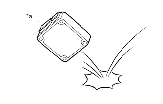
Do not drop electronic components, such as sensors or relays. If they are dropped on a hard surface, they should be replaced.
-
When cleaning the engine components with steam, protect the electronic components, air filter and emission-related components from water.
-
Never use an impact wrench to remove or install temperature switches or temperature sensors.
-
When measuring the resistance between terminals of a wire connector, insert the tester probe carefully to prevent the terminals from bending.
-
-
-
REMOVAL AND INSTALLATION OF FUEL CONTROL PARTS
-
PLACE FOR REMOVING AND INSTALLING FUEL SYSTEM PARTS
-
Work in a location with good air ventilation that does not have welders, grinders, drills, electric motors, stoves, or any other ignition sources nearby.
-
Never work in a pit or near a pit as fuel vapors will collect there.
-
-
REMOVING AND INSTALLING FUEL SYSTEM PARTS
-
Prepare a fire extinguisher before starting work.
-
To prevent static electricity, install a ground wire between the fuel changer and vehicle, and do not spray the surrounding area with water. Be careful when performing work in this area, as the floor surface will become slippery. Do not clean up gasoline spills with water, as this may cause the gasoline to spread, and possibly create a fire hazard.
-
Avoid using electric motors, work lights and other electric equipment that can cause sparks or high temperatures.
-
Avoid using iron hammers as they may create sparks.
-
Dispose of fuel-contaminated cloth separately using a fire resistant container.
-
-
-
REMOVAL AND INSTALLATION OF ENGINE INTAKE PARTS
-
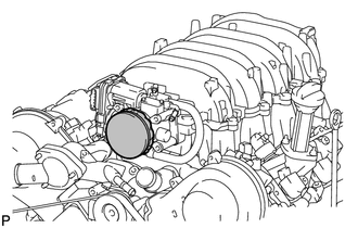
If any metal particles enter intake system parts, they may damage the engine.
-
When removing and installing intake system parts, cover the openings of the removed parts and engine openings. Use adhesive tape or other suitable materials.
-
When installing intake system parts, check that no metal particles have entered the engine or installed parts.
-
-
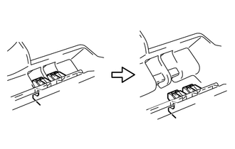
HANDLING OF HOSE CLAMPS
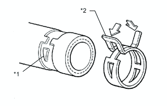
*1 Clamp Track *2 Spring Type Clamp
-
Before removing a hose, check the clamp position so that it can be reinstalled in the same position.
-
Replace any deformed or dented clamps with new ones.
-
When reusing a hose, attach the clamp on the clamp track portion of the hose.
-
For a spring type clamp, it may be necessary to spread the tabs slightly after installation by pushing them in the direction of the arrows as shown in the illustration.
-
-
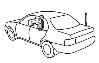
FOR VEHICLES EQUIPPED WITH MOBILE COMMUNICATION SYSTEMS
-
Install the antenna as far away from the ECU and sensors of the vehicle electronic systems as possible.
-
Install the antenna and feeder at least 20 cm (7.87 in.) away from the ECUs and sensors of the vehicle electronic systems. For details about ECU and sensor locations, refer to the section on the applicable components.
-
Keep the antenna and feeder separate from other wiring as much as possible. This will prevent signals sent from the communication equipment from affecting vehicle equipment and vice versa.
-
Check that the antenna and feeder are correctly adjusted.
-
Do not install a high-powered mobile communication system.
-
-
HEADLIGHT INSPECTION OR MAINTENANCE
-
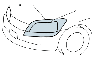
*a Illumination for 3 minutes or more prohibited if covered When the headlights are illuminated, do not cover the headlights for 3 minutes or more.
Note
As the headlight outer lens is made of resin, the resulting heat created when covering the headlight for an extended period of time may deform the headlight.
-
-
FOR AIR SUSPENSION SYSTEM
-
When lifting or jacking up the vehicle, first turn off the vehicle height control.
-
-
FOR ELECTRIC PARKING BRAKE SYSTEM
-
Precautions when working on vehicle.
-
If the vehicle needs to be tilted after stopping the vehicle on a level surface, push the electric parking brake switch twice, as the braking force may be insufficient.
Tech Tips
-
The electric parking brake determines how much braking force to apply using the yaw rate sensor value for the slope of the road.
-
Push the electric parking brake twice to apply the parking brake with the maximum braking force.
-
-
-
Parking brake forced release method.
For the parking brake forced release method: Click here
-
-
WHEN INSPECTING VEHICLES
Note
When operating the vehicle in inspection mode for an operation such as a speedometer test, a DTC may be stored. Therefore, if a warning light illuminates or warning message is displayed, after canceling inspection mode, check for DTCs using the GTS and clear the DTCs.
-
VEHICLE CONDITIONS
-
Before activating inspection mode, turn the air conditioning off, start the hybrid system with park (P) selected, and check that the engine stops within several seconds after starting (engine warm up check).
-
Activate the appropriate inspection mode and inspect the vehicle.
Tech Tips
Different types of inspection mode are available. One is Cdy-2E or Cdy-4E, and the other is Cdy-2 or Cdy-4. The following table indicates the mode appropriate for each test item.
Test Item Mode 1. Vehicle straight traveling test (side slip inspection) Cdy-2E, Cdy-4E or normal mode 2. Braking force test Normal mode 3. Speedometer test Cdy-2E or Cdy-4E 4. Exhaust gas test (idling) Cdy-2E or Cdy-4E 5. Headlight test Cdy-2E, Cdy-4E or normal mode -
Cancel inspection mode immediately after completing the inspection.
Note
Driving the vehicle without canceling inspection mode may damage the hybrid transmission.
-
-
WHEN USING A BRAKE TESTER
Tech Tips
When inspecting the brakes using a brake tester, the braking force of the rear wheels may be reduced. When the vehicle speed is 0 km/h (0 mph), the brake control system of the vehicle limits the rear brake fluid pressure to approximately 50% of the normal brake fluid pressure when driving the vehicle, in order to reduce energy consumption.
Note
-
A high-speed type brake tester cannot be used.
-
The vehicle speed should be less than 0.5 km/h (0.3 mph).
-
Follow all usage and safety procedures in the operator's manual for the brake tester.
-
Place the wheels to be tested (front or rear) onto the rollers.
-
Start the hybrid system to allow normal brake booster operation.
-
Move the shift lever to N and confirm that neutral (N) has been selected.
-
Operate the brakes to perform the test.
-
-
WHEN USING A SPEEDOMETER TESTER
CAUTION:
Be sure to perform the test in Cdy-2E or Cdy-4E
Note
Do not perform rapid starting or quick acceleration on a speedometer tester. If rapid starting or quick acceleration is performed on a speedometer tester, damage may occur to the hybrid transmission.
-
Depress the accelerator pedal slowly and gradually accelerate the vehicle, then take a measurement.
-
After the measurement, use the brakes to gradually decelerate the vehicle.
-
-
WHEN USING A CHASSIS DYNAMOMETER
CAUTION:
Be sure to perform the test in Cdy-2E or Cdy-4E
Note
Sudden acceleration or deceleration of the vehicle on a chassis dynamometer under minimal load may damage the hybrid transmission.
-
Always set an appropriate load before starting the test.
-
-
WHEN USING AN ON-VEHICLE BALANCER
CAUTION:
-
Be sure to perform the test in Cdy-2E or Cdy-4E
-
Make sure that no one is standing in-line with the spinning wheels.
Note
-
Start the hybrid system and then accelerate gradually with drive (D) selected.
-
Do not accelerate or decelerate suddenly.
-
Deceleration should be done by braking gradually.
-
Measurement should be done quickly.
-
Confirm that the vehicle is securely immobilized.
-
Follow all usage and safety procedures in the operator's manual for the wheel balancer.
-
Raise the vehicle until all 4 wheels are off the ground.
-
Support the vehicle with safety stands at an appropriate height. Make sure that the vehicle does not lean in any direction, and that the tires are completely clear of the floor.
-
Place the vibration pick-up unit into position for the wheel to be measured*.
Tech Tips
*: Different on-vehicle wheel balancers have different requirements for mounting the vibration pick-up unit(s). Refer to the operator's manual for the wheel balancer to confirm requirements for use.
-
Release the parking brake.
-
Check that no dragging force exists when turning each wheel by hand.
-
Put the wheel balancer in position.
-
Wheel balance measurement should be done by using both the hybrid system and the wheel balancer drive roller to spin the wheels.
-
-
-
PRECAUTIONS WHEN USING DRUM TESTER
-
Enter Inspection Mode to disable TRC and VSC operation when using a chassis dynamometer.
Refer to Inspection Mode Procedure: Click here
CAUTION:
-
Do not use the drum tester with any of the lock chains disconnected.
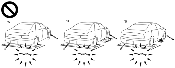
*A for 2WD *B for AWD -
Using the drum tester with a lock chain disconnected could cause the vehicle to begin moving unexpectedly.
-
Do not use the drum tester while the TRC or VSC is able to operate.
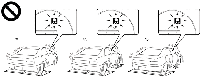
*A for 2WD *B for AWD -
TRC or VSC operation could cause the vehicle to begin moving unexpectedly.
-
-
NOTICES FOR VSC RELATED PROCEDURES
-
For VSC related parts, adjustments are required after removal and installation. Therefore, perform removal and installation only when necessary.
-
When performing VSC related procedures, be sure to strictly follow the preparation and completion procedures.
-
When performing removal and installation or replacement of VSC related parts, first disconnect the cable from the negative (-) auxiliary battery terminal.
-
-
-
ELECTRONIC SHIFT LEVER SYSTEM
-
BASIC OPERATION
-
This vehicle is equipped with an electronic shift lever system. This system electrically communicates the driver's intended shift state to the ECUs responsible for system control. The system also uses an electrically operated transmission parking lock mechanism.
Tech Tips
-
Normally, the transmission parking lock mechanism does not operate when the auxiliary battery is depleted or disconnected.
-
The shift lever position can be switched to P by the sub-battery even if the auxiliary battery is depleted or disconnected.
-
If the electronic shift lever system has been damaged due to a flood, etc., the shift state will not be able to be changed to or from park (P).When the shift state cannot be changed from park (P) to any other state, transport the vehicle by using the forced parking release mechanism to release the parking brake.
for L310: Click here
for L310F: Click here
-
There is no mechanical connection between the P position switch, shift lever and the transmission.
-
-
This system allows the driver to select the reverse (R), neutral (N), drive (D) and manual (M)* shift states using the shift lever or select the park (P) shift state by pushing the P position switch. Shift states are ECU controlled based on the actions of the driver and various conditions. Shift states can be verified using the shift position indicator in the combination meter and shift lever side shift position indicator or by using the GTS.
-
*: For enhanced engine braking.
-
-
-
-
PRECAUTIONS FOR TOWING REAR WHEEL DRIVE VEHICLES
-
Use one of the following methods to tow the vehicle.
-
If the vehicle has trouble with the chassis or drivetrain, use method 1 (flatbed truck).
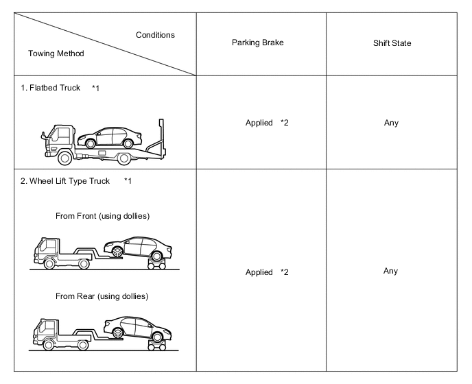
Note
-
Do not use any towing method other than those shown above.
-
*1: If the vehicle is tilted after parking on a level surface, the braking force may be insufficient as the electric parking brake determines how much braking force to apply by automatically detecting the slope of the road.
Tech Tips
*2: Push the electric parking brake twice to apply the parking brake with the maximum braking force.
-
-
If a tow truck is not available, in an emergency the vehicle may be temporarily towed using a cable or chain secured to the emergency towing eyelet(s). This should only be attempted on hard surfaced roads for short distances below 30 km/h (18 mph).
A driver must be in the vehicle to steer and operate the brakes. The vehicle's wheels, drivetrain, axles, steering and brakes must be in good condition.
Note
If the towing speed or distance exceeds the above limits, or the vehicle is towed in a backward direction with the wheels on the ground, the drivetrain or vehicle may be damaged.
-
Emergency towing procedure
-
Turn the power switch on (IG).
-
Depress the brake pedal and move the shift lever to N.
-
Release the parking brake.
-
Release the brake pedal slowly.
Note
-
Use extreme caution when towing the vehicle. Avoid sudden starts or erratic driving maneuvers which place excessive stress on the emergency towing eyelet and the cables or chains.
-
If the hybrid system is off, the power assist for the brakes and steering will not function, making steering and braking more difficult.
-
Do not turn off the power switch. Turning off the power switch may result in engagement of the parking lock, resulting in a hazardous situation or accident.
Tech Tips
-
Neutral (N) cannot be selected if the auxiliary battery is discharged or if it has been disconnected.
-
There is a possibility that neutral (N) cannot be selected when parts related to the electronic shift lever system are malfunctioning.
-
-
-
The towing methods shown below are dangerous and can damage the vehicle, so do not use them.
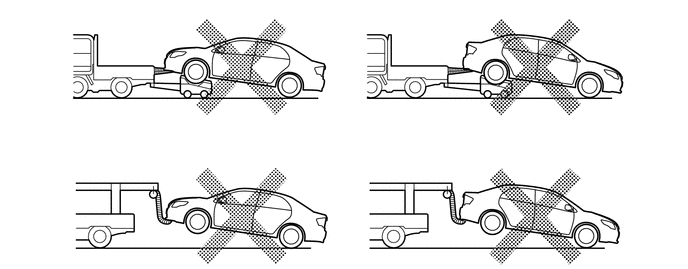
-
Do not tow the vehicle with only 2 wheels on the ground.
CAUTION:
If the vehicle is towed with only the front wheels on the ground, the steering may move, causing the vehicle to become unstable.
Note
If the vehicle is towed with only the rear wheels on the ground, the drivetrain may overheat and be damaged.
-
Do not use a sling-type towing method either from the front or rear.
Note
If a sling-type tow truck is used, damage may occur to the vehicle body.
-
-
-
PRECAUTIONS FOR TOWING ALL WHEEL DRIVE VEHICLES
-
Use one of the following methods to tow the vehicle.
-
If the vehicle has trouble with the chassis or drivetrain, use method 1 (flatbed truck).
Note
-
Do not use any towing method other than those shown above.
-
*1: If the vehicle is tilted after parking on a level surface, the braking force may be insufficient as the electric parking brake determines how much braking force to apply by automatically detecting the slope of the road.
Tech Tips
*2: Push the electric parking brake twice to apply the parking brake with the maximum braking force.
-
-
If a tow truck is not available, in an emergency the vehicle may be temporarily towed using a cable or chain secured to the emergency towing eyelet(s). This should only be attempted on hard surfaced roads for short distances below 30 km/h (18 mph).
A driver must be in the vehicle to steer and operate the brakes. The vehicle's wheels, drivetrain, axles, steering and brakes must be in good condition.
Note
If the towing speed or distance exceeds the above limits, or the vehicle is towed in a backward direction with any of the wheels on the ground, the drivetrain may be damaged.
-
Emergency towing procedure
-
Turn the power switch on (IG).
-
Depress the brake pedal and move the shift lever to N.
-
Release the parking brake.
-
Release the brake pedal slowly.
Note
-
Use extreme caution when towing the vehicle. Avoid sudden starts or erratic driving maneuvers which place excessive stress on the emergency towing eyelet and the cables or chains.
-
If the hybrid system is off, the power assist for the brakes and steering will not function, making steering and braking more difficult.
-
Do not turn off the power switch. Turning off the power switch may result in engagement of the parking lock, resulting in a hazardous situation or accident.
Tech Tips
-
Neutral (N) cannot be selected if the auxiliary battery is discharged or if it has been disconnected.
-
There is a possibility that neutral (N) cannot be selected when parts related to the electronic shift lever system are malfunctioning.
-
-
-
The towing methods shown below are dangerous and can damage the vehicle, so do not use them.
-
Do not tow the vehicle with only 2 wheels on the ground.
Note
If the vehicle is towed with only the 2 wheels on the ground, the drivetrain may overheat and be damaged or the wheels may come off the dollies.
-
Do not use a sling-type towing method either from the front or rear.
Note
If a sling-type tow truck is used, damage may occur to the vehicle body.
-
-
-
WARNING NOTIFICATION FUNCTION
Note
-
Before performing inspections or repairs which may cause warning messages or DTCs to occur, such as a simulation test or road test, it is necessary to activate warning notification restraint mode so that the G-BOOK center does not recognize the warnings as real ones.
-
Warning notification restraint mode can be entered by using the GTS or operating the multi-display assembly.
Tech Tips
The warning notification function sends a warning ON signal, received from the combination meter assembly via CAN communication, to the G-BOOK center using the G-BOOK device if a warning is displayed in the vehicle due to a vehicle malfunction.
-
Warning notification restraint mode
Tech Tips
To cancel warning notification restraint mode, turn the power switch off and on (IG) to display the service mode screen and cancel warning notification restraint mode.
-
Warning notification restraint mode (Using the GTS)
-
Turn the power switch off.
-
Connect the GTS to the DLC3.
-
Turn the power switch on (READY).
-
Turn the GTS on.
-
Enter the following menus: Powertrain / Engine and ECT / Trouble Codes.
-
-
Warning notification restraint mode (Using the multi-display assembly)
-
Enter diagnostic mode of navigation system.
-
-
-
-
STRICT PROHIBITION OF MANUAL EMERGENCY CALL USING EMERGENCY CALL SERVICE
-
Do not make an emergency call when not in emergency situations. For inspections, use the manual maintenance check.
Note
-
If the emergency call service is used to connect to the G-BOOK center when not in an emergency situation, an unnecessary workload will be generated at the G-BOOK center. This may cause a delayed response by the G-BOOK center to other emergency calls.
-
If emergency vehicles are dispatched due to an accidental operation of the emergency call switch, you may be charged or punished according to related laws.
-
-
If the emergency call switch is accidentally operated;
-
If the emergency call switch is accidentally operated, contact the G-BOOK center to tell them that the call was made by mistake.
-
An emergency call cannot be halted or finished from the vehicle. Only the G-BOOK center can halt or finish the call.
-
If the G-BOOK center cannot be informed that the call was made by mistake, the center will report to authorities, emergency facilities and dealerships in compliance with its agreements. As a result, emergency vehicles may be dispatched.
-
-
-
FOR VEHICLES EQUIPPED WITH CATALYTIC CONVERTER
CAUTION:
If a large amount of unburned gasoline or gasoline vapors flow into the converter, it may cause converter overheating and create a fire hazard. To prevent this, observe the following precautions:
-
Use only unleaded gasoline.
-
Avoid performing unnecessary spark tests.
-
Perform a spark test only when absolutely necessary. Perform this test as rapidly as possible.
-
While testing, never race the engine unless instructed.
-
-
Avoid a prolonged engine compression measurement. Engine compression measurements must be performed as rapidly as possible.
-
Do not run the engine when the fuel tank is nearly empty. This may cause the engine to misfire and create an extra load on the converter.
-
-
INSPECTION AND ADJUSTMENT OF JOINT ANGLE DURING REMOVAL AND INSTALLATION OF PROPELLER SHAFT
-
When performing operations which involve the removal and installation of the propeller shaft, always check the joint angle. Make adjustments if necessary.
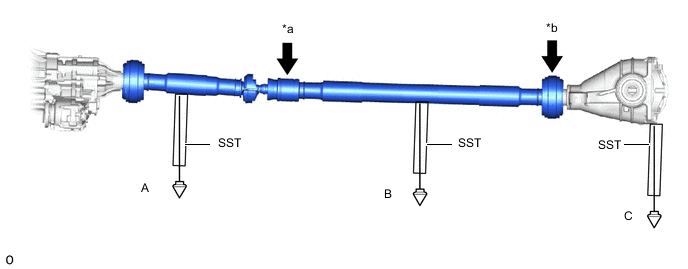
*a No. 2 Joint Angle *b No. 3 Joint Angle
-