CAN COMMUNICATION SYSTEM Short to GND in CAN Bus Line
DESCRIPTION
There may be a short circuit between the CAN bus lines and GND when the resistance between terminals 6 (CANH) and 4 (CG) or terminals 14 (CANL) and 4 (CG) of the DLC3 is below 200 Ω.
| Symptom | Trouble Area |
|---|---|
| The resistance between terminals 6 (CANH) and 4 (CG) or terminals 14 (CANL) and 4 (CG) of the DLC3 is below 200 Ω. |
|
-
*1: w/ Air Conditioning System, except 5L-E
-
*2: w/ Smart Entry and Start System
-
*3: for LED Headlight
-
*4: w/ Airbag System
-
*5: w/ ABS
-
*6: w/ VSC
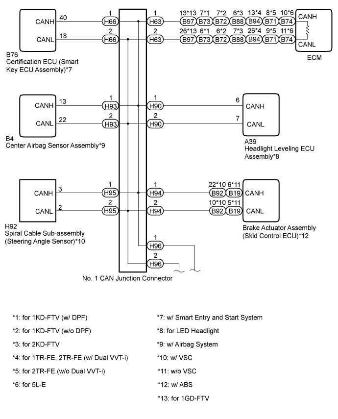
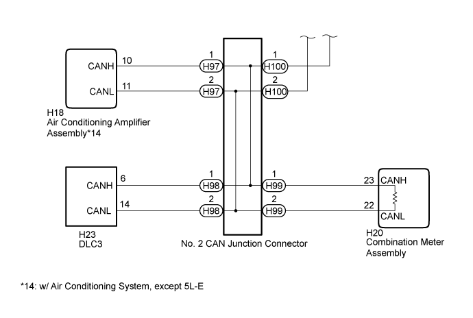
WIRING DIAGRAM
INSPECTION PROCEDURE
Note
For vehicles with a smart entry and start system:
Before replacing the certification ECU (smart key ECU assembly), refer to the smart entry and start system Click here.
Tech Tips
Operating the ignition switch, any switches or any doors triggers related ECU and sensor communication with the CAN, which causes resistance variation.
PROCEDURE
-
DISCONNECT CABLE FROM NEGATIVE BATTERY TERMINAL
-
Disconnect the cable from the negative (-) battery terminal before measuring the resistances of the CAN main wire and the CAN branch wire.
CAUTION:
For vehicles with an airbag system:
Wait at least 90 seconds after disconnecting the cable from the negative (-) battery terminal to disable the SRS system.
Note
When disconnecting the cable, some systems need to be initialized after the cable is reconnected Click here.
NEXT 
-
-
CHECK FOR SHORT TO GND IN CAN BUS WIRE (DLC3 CAN BRANCH WIRE)
-
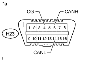
Text in Illustration *a Front view of DLC3 Disconnect the H98 No. 2 CAN junction connector.
-
Measure the resistance according to the value(s) in the table below.
Standard Resistance Tester Connection Switch Condition Specified Condition H23-6 (CANH) - H23-4 (CG) Ignition switch off 200 Ω or higher H23-14 (CANL) - H23-4 (CG) Ignition switch off 200 Ω or higher
NG 
REPAIR OR REPLACE CAN BRANCH WIRE CONNECTED TO DLC3 (CANH, CANL)
OK
-
-
CONNECT CONNECTOR
-
Reconnect the H98 No. 2 CAN junction connector.
NEXT
-
-
CHECK FOR SHORT TO GND IN CAN BUS WIRE (NO. 1 CAN JUNCTION CONNECTOR SIDE)
-
Text in Illustration *a Front view of DLC3 Disconnect the H96 No. 1 CAN junction connector.
-
Measure the resistance according to the value(s) in the table below.
Standard Resistance Tester Connection Switch Condition Specified Condition H23-6 (CANH) - H23-4 (CG) Ignition switch off 200 Ω or higher H23-14 (CANL) - H23-4 (CG) Ignition switch off 200 Ω or higher
NG 
CONNECT CONNECTOR Click here
OK
-
-
CHECK FOR SHORT TO GND IN CAN BUS WIRE (NO. 1 CAN JUNCTION CONNECTOR - CERTIFICATION ECU)
Note
For vehicles without a smart entry and start system, go to "Check for Short to GND in CAN Bus Wires (No. 1 CAN Junction Connector - Headlight Leveling ECU Assembly)".
-

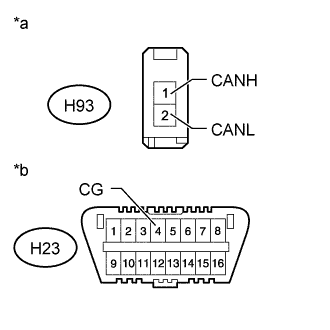
Text in Illustration *a Front view of wire harness connector
(to No. 1 CAN Junction Connector)
*b Front view of DLC3 Disconnect the No. 1 CAN junction connector.
-
Measure the resistance according to the value(s) in the table below.
Standard Resistance Tester Connection Switch Condition Specified Condition H66-1 (CANH) - H23-4 (CG) Ignition switch off 200 Ω or higher H66-2 (CANL) - H23-4 (CG) Ignition switch off 200 Ω or higher
NG
CONNECT CONNECTOR Click here
OK
-
-
CHECK FOR SHORT TO GND IN CAN BUS WIRE (NO. 1 CAN JUNCTION CONNECTOR - HEADLIGHT LEVELING ECU ASSEMBLY)
Note
For vehicles with a halogen headlight, go to "Check for Short to GND in CAN Bus Wires (No. 1 CAN Junction Connector - Center Airbag Sensor Assembly)".
-

Text in Illustration *a Front view of wire harness connector
(to No. 1 CAN Junction Connector)
*b Front view of DLC3 Disconnect the No. 1 CAN junction connector.
-
Measure the resistance according to the value(s) in the table below.
Standard Resistance Tester Connection Switch Condition Specified Condition H90-1 (CANH) - H23-4 (CG) Ignition switch off 200 Ω or higher H90-2 (CANL) - H23-4 (CG) Ignition switch off 200 Ω or higher
NG
CONNECT CONNECTOR Click here
OK
-
-
CHECK FOR SHORT TO GND IN CAN BUS WIRE (NO. 1 CAN JUNCTION CONNECTOR - CENTER AIRBAG SENSOR ASSEMBLY)
Note
For vehicles without an airbag system, go to "Check for Short to GND in CAN Bus Wires (No. 1 CAN Junction Connector - Brake Actuator Assembly)".
-
Text in Illustration *a Front view of wire harness connector
(to No. 1 CAN Junction Connector)
*b Front view of DLC3 Disconnect the No. 1 CAN junction connector.
-
Measure the resistance according to the value(s) in the table below.
Standard Resistance Tester Connection Switch Condition Specified Condition H93-1 (CANH) - H23-4 (CG) Ignition switch off 200 Ω or higher H93-2 (CANL) - H23-4 (CG) Ignition switch off 200 Ω or higher
NG
CONNECT CONNECTOR Click here
OK
-
-
CHECK FOR SHORT TO GND IN CAN BUS WIRE (NO. 1 CAN JUNCTION CONNECTOR - BRAKE ACTUATOR ASSEMBLY)
Note
For vehicles without an ABS, go to "Check for Short to GND in CAN Bus Wires (No. 1 CAN Junction Connector - ECM)".
-

Text in Illustration *a Front view of wire harness connector
(to No. 1 CAN Junction Connector)
*b Front view of DLC3 Disconnect the No. 1 CAN junction connector.
-
Measure the resistance according to the value(s) in the table below.
Standard Resistance Tester Connection Switch Condition Specified Condition H94-1 (CANH) - H23-4 (CG) Ignition switch off 200 Ω or higher H94-2 (CANL) - H23-4 (CG) Ignition switch off 200 Ω or higher
NG
CONNECT CONNECTOR Click here
OK
-
-
CHECK FOR SHORT TO GND IN CAN BUS WIRE (NO. 1 CAN JUNCTION CONNECTOR - SPIRAL CABLE SUB-ASSEMBLY)
Note
For vehicles without a VSC, go to "Check for Short to GND in CAN Bus Wires (No. 1 CAN Junction Connector - ECM)".
-
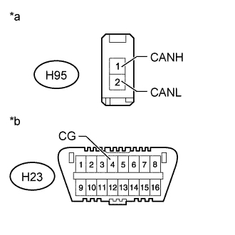
Text in Illustration *a Front view of wire harness connector
(to No. 1 CAN Junction Connector)
*b Front view of DLC3 Disconnect the No. 1 CAN junction connector.
-
Measure the resistance according to the value(s) in the table below.
Standard Resistance Tester Connection Switch Condition Specified Condition H95-1 (CANH) - H23-4 (CG) Ignition switch off 200 Ω or higher H95-2 (CANL) - H23-4 (CG) Ignition switch off 200 Ω or higher
NG
CONNECT CONNECTOR Click here
OK
-
-
CHECK FOR SHORT TO GND IN CAN BUS WIRE (NO. 1 CAN JUNCTION CONNECTOR - ECM)
-
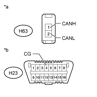
Text in Illustration *a Front view of wire harness connector
(to No. 1 CAN Junction Connector)
*b Front view of DLC3 Disconnect the No. 1 CAN junction connector.
-
Measure the resistance according to the value(s) in the table below.
Standard Resistance Tester Connection Switch Condition Specified Condition H63-1 (CANH) - H23-4 (CG) Ignition switch off 200 Ω or higher H63-2 (CANL) - H23-4 (CG) Ignition switch off 200 Ω or higher
NG
CONNECT CONNECTOR Click here
OK 
REPLACE NO. 1 CAN JUNCTION CONNECTOR
-
-
CONNECT CONNECTOR
-
Reconnect the No. 1 CAN junction connector(s).
NEXT
-
-
CHECK FOR SHORT TO GND IN CAN BUS WIRE (CERTIFICATION ECU)
-
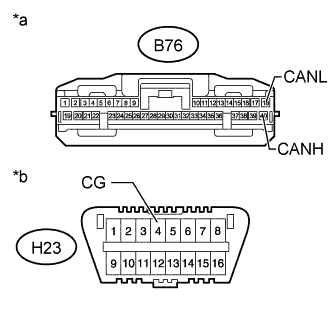
Text in Illustration *a Front view of wire harness connector
(to Certification ECU [Smart Key ECU Assembly])
*b Front view of DLC3 Disconnect the certification ECU (smart key ECU assembly) connector.
-
Measure the resistance according to the value(s) in the table below.
Standard Resistance Tester Connection Switch Condition Specified Condition B76-40 (CANH) - H23-4 (CG) Ignition switch off 200 Ω or higher B76-18 (CANL) - H23-4 (CG) Ignition switch off 200 Ω or higher
NG
REPAIR OR REPLACE CAN BRANCH WIRE CONNECTED TO CERTIFICATION ECU (CANH, CANL)
OK
REPLACE CERTIFICATION ECU (SMART KEY ECU ASSEMBLY)
-
-
CONNECT CONNECTOR
-
Reconnect the No. 1 CAN junction connector(s).
NEXT
-
-
CHECK FOR SHORT TO GND IN CAN BUS WIRE (HEADLIGHT LEVELING ECU ASSEMBLY)
-
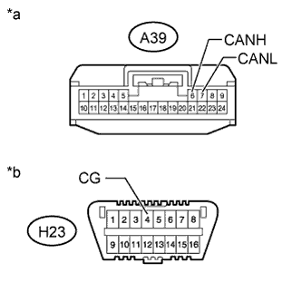
Text in Illustration *a Front view of wire harness connector
(to Headlight Leveling ECU Assembly)
*b Front view of DLC3 Disconnect the headlight leveling ECU assembly connector.
-
Measure the resistance according to the value(s) in the table below.
Standard Resistance Tester Connection Switch Condition Specified Condition A39-6 (CANH) - H23-4 (CG) Ignition switch off 200 Ω or higher A39-7 (CANL) - H23-4 (CG) Ignition switch off 200 Ω or higher Result Result Proceed to OK (for LHD) A OK (for RHD) B NG C
B
REPLACE HEADLIGHT LEVELING ECU ASSEMBLY Click here
C
REPAIR OR REPLACE CAN BRANCH WIRE CONNECTED TO HEADLIGHT LEVELING ECU ASSEMBLY (CANH, CANL)
A
REPLACE HEADLIGHT LEVELING ECU ASSEMBLY Click here
-
-
CONNECT CONNECTOR
-
Reconnect the No. 1 CAN junction connector(s).
NEXT
-
-
CHECK FOR SHORT TO GND IN CAN BUS WIRE (CENTER AIRBAG SENSOR ASSEMBLY)
-
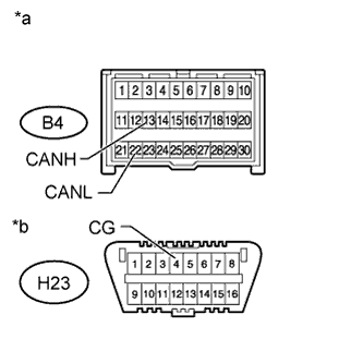
Text in Illustration *a Front view of wire harness connector
(to Center Airbag Sensor Assembly)
*b Front view of DLC3 Disconnect the center airbag sensor assembly connector Click here.
-
Measure the resistance according to the value(s) in the table below.
Standard Resistance Tester Connection Switch Condition Specified Condition B4-13 (CANH) - H23-4 (CG) Ignition switch off 200 Ω or higher B4-22 (CANL) - H23-4 (CG) Ignition switch off 200 Ω or higher
NG
REPAIR OR REPLACE CAN BRANCH WIRE CONNECTED TO CENTER AIRBAG SENSOR ASSEMBLY (CANH, CANL)
OK
REPLACE CENTER AIRBAG SENSOR ASSEMBLY Click here
-
-
CONNECT CONNECTOR
-
Reconnect the No. 1 CAN junction connector(s).
NEXT
-
-
CHECK FOR SHORT TO GND IN CAN BUS WIRE (BRAKE ACTUATOR ASSEMBLY)
-
Disconnect the brake actuator assembly (skid control ECU) connector.
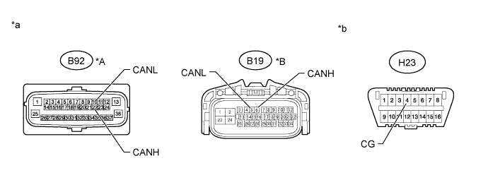
Text in Illustration *A w/ VSC *B w/o VSC *a Front view of wire harness connector
(to Brake Actuator Assembly [Skid Control ECU])
*b Front view of DLC3 -
Measure the resistance according to the value(s) in the table below.
Standard Resistance w/ VSC Tester Connection Switch Condition Specified Condition B92-22 (CANH) - H23-4 (CG) Ignition switch off 200 Ω or higher B92-10 (CANL) - H23-4 (CG) Ignition switch off 200 Ω or higher w/o VSC Tester Connection Switch Condition Specified Condition B19-6 (CANH) - H23-4 (CG) Ignition switch off 200 Ω or higher B19-5 (CANL) - H23-4 (CG) Ignition switch off 200 Ω or higher Result Result Proceed to OK (w/ VSC) A OK (w/o VSC) B NG C
B
REPLACE BRAKE ACTUATOR ASSEMBLY (SKID CONTROL ECU) Click here
C
REPAIR OR REPLACE CAN BRANCH WIRE CONNECTED TO BRAKE ACTUATOR ASSEMBLY (CANH, CANL)
A
REPLACE BRAKE ACTUATOR ASSEMBLY (SKID CONTROL ECU) Click here
-
-
CONNECT CONNECTOR
-
Reconnect the No. 1 CAN junction connector(s).
NEXT
-
-
CHECK FOR SHORT TO GND IN CAN BUS WIRE (SPIRAL CABLE SUB-ASSEMBLY)
-
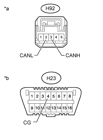
Text in Illustration *a Front view of wire harness connector
(to Spiral Cable Sub-assembly [Steering Angle Sensor])
*b Front view of DLC3 Disconnect the spiral cable sub-assembly (steering angle sensor) connector.
-
Measure the resistance according to the value(s) in the table below.
Standard Resistance Tester Connection Switch Condition Specified Condition H92-3 (CANH) - H23-4 (CG) Ignition switch off 200 Ω or higher H92-2 (CANL) - H23-4 (CG) Ignition switch off 200 Ω or higher
NG
REPAIR OR REPLACE CAN BRANCH WIRE CONNECTED TO SPIRAL CABLE SUB-ASSEMBLY (CANH, CANL)
OK
REPLACE SPIRAL CABLE SUB-ASSEMBLY (STEERING ANGLE SENSOR) Click here
-
-
CONNECT CONNECTOR
-
Reconnect the No. 1 CAN junction connector(s).
NEXT
-
-
CHECK FOR SHORT TO GND IN CAN BUS WIRE (ECM)
-
Disconnect the ECM connector.
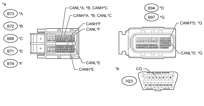
Text in Illustration *A for 1KD-FTV (w/ DPF) *B for 1KD-FTV (w/o DPF) *C for 2KD-FTV *D for 1TR-FE, 2TR-FE (w/ Dual VVT-i) *E for 2TR-FE (w/o Dual VVT-i) *F for 5L-E *G for 1GD-FTV - - *a Front view of wire harness connector
(to ECM)
*b Front view of DLC3 -
Measure the resistance according to the value(s) in the table below.
Standard Resistance for 1KD-FTV (w/ DPF) Tester Connection Switch Condition Specified Condition B73-7 (CANH) - H23-4 (CG) Ignition switch off 200 Ω or higher B73-6 (CANL) - H23-4 (CG) Ignition switch off 200 Ω or higher for 1KD-FTV (w/o DPF) Tester Connection Switch Condition Specified Condition B72-7 (CANH) - H23-4 (CG) Ignition switch off 200 Ω or higher B72-6 (CANL) - H23-4 (CG) Ignition switch off 200 Ω or higher for 2KD-FTV Tester Connection Switch Condition Specified Condition B88-6 (CANH) - H23-4 (CG) Ignition switch off 200 Ω or higher B88-7 (CANL) - H23-4 (CG) Ignition switch off 200 Ω or higher for 1TR-FE, 2TR-FE (w/ Dual VVT-i) Tester Connection Switch Condition Specified Condition B94-13 (CANH) - H23-4 (CG) Ignition switch off 200 Ω or higher B94-26 (CANL) - H23-4 (CG) Ignition switch off 200 Ω or higher for 2TR-FE (w/o Dual VVT-i) Tester Connection Switch Condition Specified Condition B71-8 (CANH) - H23-4 (CG) Ignition switch off 200 Ω or higher B71-9 (CANL) - H23-4 (CG) Ignition switch off 200 Ω or higher for 5L-E Tester Connection Switch Condition Specified Condition B74-10 (CANH) - H23-4 (CG) Ignition switch off 200 Ω or higher B74-11 (CANL) - H23-4 (CG) Ignition switch off 200 Ω or higher for 1GD-FTV Tester Connection Switch Condition Specified Condition B97-13 (CANH) - H23-4 (CG) Ignition switch off 200 Ω or higher B97-26 (CANL) - H23-4 (CG) Ignition switch off 200 Ω or higher Tech Tips
*: Replacement procedure:
-
for 1KD-FTV Click here.
-
for 2KD-FTV Click here.
-
for 1TR-FE Click here.
-
for 2TR-FE (w/o Dual VVT-i) Click here.
-
for 2TR-FE (w/ Dual VVT-i) Click here.
-
for 5L-E Click here.
-
for 1GD-FTV Click here.
-
NG
REPAIR OR REPLACE CAN MAIN WIRE CONNECTED TO ECM (CANH, CANL)
OK
REPLACE ECM*
-
-
CONNECT CONNECTOR
-
Reconnect all wire harness CAN junction connectors.
NEXT
-
-
CHECK FOR SHORT TO GND IN CAN BUS WIRE (NO. 2 CAN JUNCTION CONNECTOR - NO. 1 CAN JUNCTION CONNECTOR)
-

Text in Illustration *a Front view of wire harness connector
(to No. 2 CAN Junction Connector)
*b Front view of DLC3 Disconnect the No. 2 CAN junction connector.
-
Measure the resistance according to the value(s) in the table below.
Standard Resistance Tester Connection Switch Condition Specified Condition H100-1 (CANH) - H23-4 (CG) Ignition switch off 200 Ω or higher H100-2 (CANL) - H23-4 (CG) Ignition switch off 200 Ω or higher
NG
REPAIR OR REPLACE CAN MAIN WIRE OR CONNECTOR (NO. 2 CAN JUNCTION CONNECTOR - NO. 1 CAN JUNCTION CONNECTOR)
OK
-
-
CHECK FOR SHORT TO GND IN CAN BUS WIRE (NO. 2 CAN JUNCTION CONNECTOR - AIR CONDITIONING AMPLIFIER ASSEMBLY)
Note
For vehicles without an air conditioning system or with 5L-E engine type, go to "Check for Short to GND in CAN Bus Wires (No. 2 CAN Junction Connector - Combination Meter Assembly)".
-

Text in Illustration *a Front view of wire harness connector
(to No. 2 CAN Junction Connector)
*b Front view of DLC3 Disconnect the No. 2 CAN junction connector.
-
Measure the resistance according to the value(s) in the table below.
Standard Resistance Tester Connection Switch Condition Specified Condition H97-1 (CANH) - H23-4 (CG) Ignition switch off 200 Ω or higher H97-2 (CANL) - H23-4 (CG) Ignition switch off 200 Ω or higher
NG
CONNECT CONNECTOR Click here
OK
-
-
CHECK FOR SHORT TO GND IN CAN BUS WIRE (NO. 2 CAN JUNCTION CONNECTOR - COMBINATION METER ASSEMBLY)
-

Text in Illustration *a Front view of wire harness connector
(to No. 2 CAN Junction Connector)
*b Front view of DLC3 Disconnect the No. 2 CAN junction connector.
-
Measure the resistance according to the value(s) in the table below.
Standard Resistance Tester Connection Switch Condition Specified Condition H99-1 (CANH) - H23-4 (CG) Ignition switch off 200 Ω or higher H99-2 (CANL) - H23-4 (CG) Ignition switch off 200 Ω or higher
NG
CONNECT CONNECTOR Click here
OK
REPLACE NO. 2 CAN JUNCTION CONNECTOR
-
-
CONNECT CONNECTOR
-
Reconnect the No. 2 CAN junction connector(s).
NEXT
-
-
CHECK FOR SHORT TO GND IN CAN BUS WIRE (AIR CONDITIONING AMPLIFIER ASSEMBLY)
-
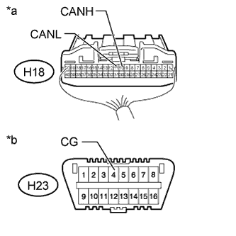
Text in Illustration *a Rear view of wire harness connector
(to Air Conditioning Amplifier Assembly)
*b Front view of DLC3 Disconnect the air conditioning amplifier assembly connector.
-
Measure the resistance according to the value(s) in the table below.
Standard Resistance Tester Connection Switch Condition Specified Condition H18-10 (CANH) - H23-4 (CG) Ignition switch off 200 Ω or higher H18-11 (CANL) - H23-4 (CG) Ignition switch off 200 Ω or higher
NG
REPAIR OR REPLACE CAN BRANCH WIRE CONNECTED TO AIR CONDITIONING AMPLIFIER ASSEMBLY (CANH, CANL)
OK
REPLACE AIR CONDITIONING AMPLIFIER ASSEMBLY Click here
-
-
CONNECT CONNECTOR
-
Reconnect the No. 2 CAN junction connector(s).
NEXT
-
-
CHECK FOR SHORT TO GND IN CAN BUS WIRE (COMBINATION METER ASSEMBLY)
-
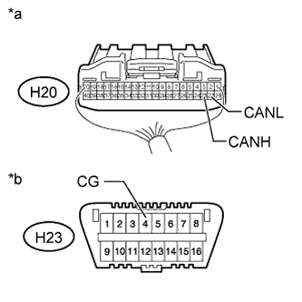
Text in Illustration *a Rear view of wire harness connector
(to Combination Meter Assembly)
*b Front view of DLC3 Disconnect the combination meter assembly connector.
-
Measure the resistance according to the value(s) in the table below.
Standard Resistance Tester Connection Switch Condition Specified Condition H20-23 (CANH) - H23-4 (CG) Ignition switch off 200 Ω or higher H20-22 (CANL) - H23-4 (CG) Ignition switch off 200 Ω or higher
NG
REPAIR OR REPLACE CAN MAIN WIRE CONNECTED TO COMBINATION METER ASSEMBLY (CANH, CANL)
OK
REPLACE COMBINATION METER ASSEMBLY Click here
-