DYNAMIC RADAR CRUISE CONTROL SYSTEM, Diagnostic DTC:C1A05, C1A4B

| DTC Code | DTC Name |
|---|---|
| C1A05 | Stop Light Switch Circuit |
| C1A4B | Stop Light Relay Circuit |
DESCRIPTION
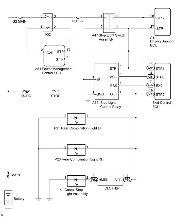
The skid control ECU receives a signal from the driving support ECU and operates the brake actuator. The skid control ECU operates the brake actuator and at the same time illuminates the stop light by operating the stop light control relay.
When the brake pedal is depressed, the stop light switch assembly sends a signal to the driving support ECU. Upon receiving the signal, the driving support ECU cancels the dynamic radar cruise control system. Even if there is a malfunction in the stop light switch signal circuit while the cruise control is operating, normal driving is maintained due to the fail-safe function. Dynamic radar cruise control is canceled when positive battery voltage is applied to terminal STP-.
When the brake pedal is released, positive voltage is applied to terminal ST1- of the driving support ECU through the ECU IG2 fuse and the stop light switch assembly, and the driving support ECU operates the dynamic radar cruise control.
| DTC No. | DTC Detection Condition | Trouble Area |
|---|---|---|
| C1A05 | Voltages of terminals ST1- and STP- of driving support ECU are both below 1 V for 1 second |
|
| C1A4B | This trouble code is output when the ECM detects the stop light control relay error signal from the skid control ECU for 1 second while the dynamic cruise control is operating. |
|
WIRING DIAGRAM
INSPECTION PROCEDURE
Note
Inspect the fuses for circuits related to this system before performing the following inspection procedure.
PROCEDURE
-
READ VALUE USING INTELLIGENT TESTER (STOP LIGHT SWITCH ASSEMBLY)
-
Connect the intelligent tester to the DLC3.
-
Turn the power switch on (IG).
-
Turn the tester on.
-
Enter the following menus: Powertrain / Radar Cruise / Data List.
-
Check the Data List for proper functioning of the stop light switch.
Radar Cruise Tester Display Measurement Item/Range Normal Condition Diagnostic Note Stop Light SW 1 (M CPU) Stop light switch (Main-CPU) signal/ON or OFF ON: Brake pedal depressed
OFF: Brake pedal released
- Stop Light SW 1 (S CPU) Stop light switch (Sub-CPU) signal/ON or OFF ON: Brake pedal depressed
OFF: Brake pedal released
- Stop Light SW 2 (M CPU) Stop light switch (Main-CPU) signal/ON or OFF ON: Brake pedal depressed
OFF: Brake pedal released
- OK Display changes according to brake pedal operation described in above table.
NG 
CHECK HARNESS AND CONNECTOR (STOP LIGHT SWITCH ASSEMBLY POWER SOURCE) Click here
OK 
-
-
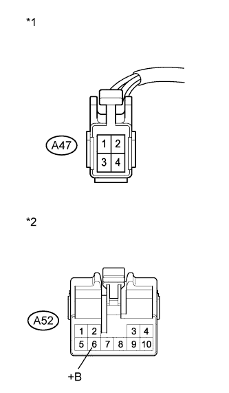
CHECK HARNESS AND CONNECTOR (STOP LIGHT CONTROL RELAY POWER SOURCE)
-
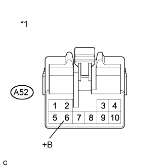
Text in Illustration *1 Front view of wire harness connector
(to Stop Light Control Relay)
Disconnect the stop light control relay connector.
-
Measure the voltage according to the value(s) in the table below.
Standard Voltage Tester Connection Condition Specified Condition A52-6 (+B) - Body ground Always 11 to 14 V -
Reconnect the stop light control relay connector.
NG 
REPAIR OR REPLACE HARNESS OR CONNECTOR (STOP LIGHT CONTROL RELAY - STOP FUSE)
OK
-
-
CHECK HARNESS AND CONNECTOR (STOP LIGHT CONTROL RELAY - BODY GROUND)
-
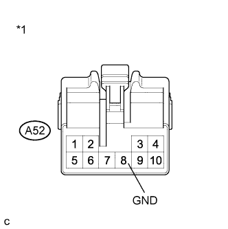
Text in Illustration *1 Front view of wire harness connector
(to Stop Light Control Relay)
Disconnect the stop light control relay connector.
-
Measure the resistance according to the value(s) in the table below.
Standard Resistance (Check for Open) Tester Connection Condition Specified Condition A52-8 (GND) - Body ground Always Below 1 Ω -
Reconnect the stop light control relay connector.
NG
REPAIR OR REPLACE HARNESS OR CONNECTOR (STOP LIGHT CONTROL RELAY - BODY GROUND)
OK
-
-
CHECK HARNESS AND CONNECTOR (STOP LIGHT CONTROL RELAY - STOP LIGHT SWITCH ASSEMBLY)
-
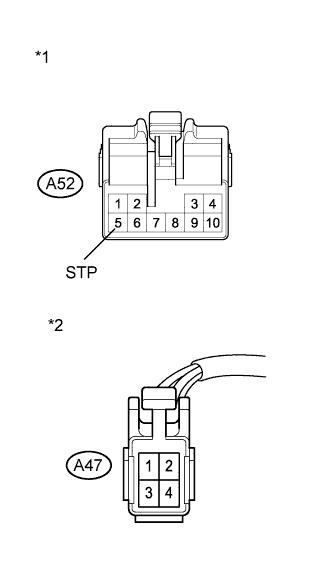
Text in Illustration *1 Front view of wire harness connector
(to Stop Light Control Relay)
*2 Front view of wire harness connector
(to Stop Light Switch Assembly)
Disconnect the stop light control relay connector.
-
Disconnect the stop light switch assembly connector.
-
Measure the resistance according to the value(s) in the table below.
Standard Resistance (Check for Open) Tester Connection Condition Specified Condition A47-1 - A52-5 (STP) Always Below 1 Ω Standard Resistance (Check for Short) Tester Connection Condition Specified Condition A47-1 or A52-5 (STP) - Body ground Always 10 kΩ or higher -
Reconnect the stop light switch assembly connector.
-
Reconnect the stop light control relay connector.
NG
REPAIR OR REPLACE HARNESS OR CONNECTOR (STOP LIGHT CONTROL RELAY - STOP LIGHT SWITCH ASSEMBLY)
OK
-
-
CHECK HARNESS AND CONNECTOR (STOP LIGHT SWITCH ASSEMBLY - SKID CONTROL ECU)
-
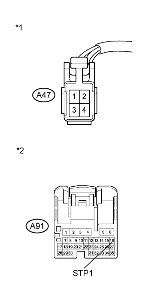
Text in Illustration *1 Front view of wire harness connector
(to Stop Light Switch Assembly)
*2 Front view of wire harness connector
(to Skid Control ECU)
Disconnect the stop light switch assembly connector.
-
Disconnect the skid control ECU connector.
-
Measure the resistance according to the value(s) in the table below.
Standard Resistance (Check for Open) Tester Connection Condition Specified Condition A47-1 - A91-16 (STP1) Always Below 1 Ω Standard Resistance (Check for Short) Tester Connection Condition Specified Condition A47-1 or A91-16 (STP1) - Body ground Always 10 kΩ or higher -
Reconnect the stop light switch assembly connector.
-
Reconnect the skid control ECU connector.
NG
REPAIR OR REPLACE HARNESS OR CONNECTOR (STOP LIGHT SWITCH ASSEMBLY - SKID CONTROL ECU)
OK
-
-
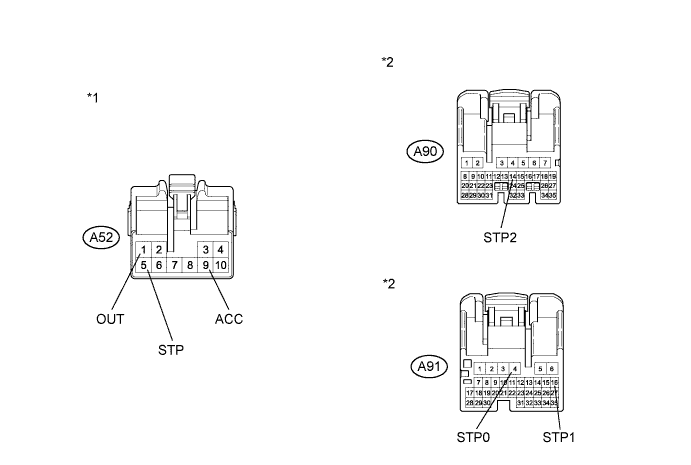
CHECK HARNESS AND CONNECTOR (STOP LIGHT CONTROL RELAY - SKID CONTROL ECU)
-
Disconnect the stop light control relay connector.
-
Disconnect the skid control ECU connectors.
-
Measure the resistance according to the value(s) in the table below.
Standard Resistance (Check for Open) Tester Connection Switch Condition Specified Condition A52-1 (OUT) - A90-14 (STP2) Always Below 1 Ω A52-5 (STP) - A91-16 (STP1) Always Below 1 Ω A52-9 (ACC) - A91-4 (STP0) Always Below 1 Ω Standard Resistance (Check for Short) Tester Connection Switch Condition Specified Condition A52-1 (OUT) or A90-14 (STP2) - Body ground Always Below 1 Ω A52-5 (STP) or A91-16 (STP1) - Body ground Always Below 1 Ω A52-9 (ACC) or A91-4 (STP0) - Body ground Always Below 1 Ω -
Reconnect the stop light control relay connector.
-
Reconnect the skid control ECU connectors.
Text in Illustration *1 Front view of wire harness connector
(to Stop Light Control Relay)
*2 Front view of wire harness connector
(to Skid Control ECU)
NG
REPAIR OR REPLACE HARNESS OR CONNECTOR (STOP LIGHT CONTROL RELAY - SKID CONTROL ECU)
OK
-
-
INSPECT STOP LIGHT CONTROL RELAY
-
Inspect the stop light control relay Click here.
NG
REPLACE STOP LIGHT CONTROL RELAY Click here
OK
-
-
REPLACE SKID CONTROL ECU
-
Replace the skid control ECU Click here.
NEXT
-
-
CHECK WHETHER DTC OUTPUT RECURS (DTC C1A05 OR C1A4B)
-
Connect the intelligent tester to the DLC3.
-
Turn the power switch on (IG).
-
Clear the DTCs Click here.
-
Perform the following to make sure that the DTC detection conditions are met.
Tech Tips
If the detection conditions are not met, the malfunction cannot be detected.
-
Drive the vehicle at a speed of 40 km/h (25 mph) or more.
-
Turn the cruise control main switch on.
-
Push the -SET switch to activate the cruise control.
-
-
Enter the following menus: Powertrain / Radar Cruise / DTC.
-
Read the DTCs.
Result Result Proceed to DTC is not output A DTC C1A05 or C1A4B is output B
B
REPLACE POWER MANAGEMENT CONTROL ECU Click here
A 
END
-
-
REPLACE POWER MANAGEMENT CONTROL ECU
-
Replace the power management control ECU Click here for LHD, Click here for RHD).
NEXT
-
-
CHECK WHETHER DTC OUTPUT RECURS (DTC C1A05 OR C1A4B)
-
Connect the intelligent tester to the DLC3.
-
Turn the power switch on (IG).
-
Clear the DTCs Click here.
-
Perform the following to make sure that the DTC detection conditions are met.
Tech Tips
If the detection conditions are not met, the malfunction cannot be detected.
-
Drive the vehicle at a speed of 40 km/h (25 mph) or more.
-
Turn the cruise control main switch on.
-
Push the -SET switch to activate the cruise control.
-
-
Enter the following menus: Powertrain / Radar Cruise / DTC.
-
Read the DTCs.
Result Proceed to DTC is not output A DTC C1A05 or C1A4B is output B
B
REPLACE DRIVING SUPPORT ECU Click here
A
END
-
-
CHECK HARNESS AND CONNECTOR (STOP LIGHT SWITCH ASSEMBLY POWER SOURCE)
-
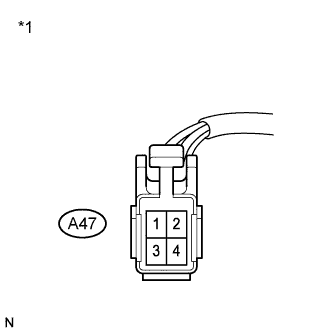
Text in Illustration *1 Front view of wire harness connector
(to Stop Light Switch Assembly)
Disconnect the stop light switch assembly connector.
-
Measure the voltage according to the value(s) in the table below.
Standard Voltage Tester Connection Condition Specified Condition A47-2 - Body ground Always 11 to 14 V -
Reconnect the stop light switch assembly connector.
NG
CHECK HARNESS AND CONNECTOR (STOP LIGHT SWITCH ASSEMBLY - STOP LIGHT CONTROL RELAY) Click here
OK
-
-
CHECK HARNESS AND CONNECTOR (STOP LIGHT SWITCH ASSEMBLY POWER SOURCE)
-
Text in Illustration *1 Front view of wire harness connector
(to Stop Light Switch Assembly)
Disconnect the stop light switch assembly connector.
-
Turn the power switch on (IG).
-
Measure the voltage according to the value(s) in the table below.
Standard Voltage Tester Connection Condition Specified Condition A47-4 - Body ground Power switch on (IG) 11 to 14 V -
Reconnect the stop light switch assembly connector.
NG
REPAIR OR REPLACE HARNESS OR CONNECTOR (STOP LIGHT SWITCH ASSEMBLY - IG2 RELAY)
OK
-
-
INSPECT STOP LIGHT SWITCH ASSEMBLY
-
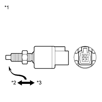
Text in Illustration *1 Component without harness connected
(Stop Light Switch Assembly)
*2 Free *3 Pushed in Remove the stop light switch assembly Click here.
-
Measure the resistance according to the value(s) in the table below.
Standard Resistance Tester Connection Switch Condition Specified Condition 1 - 2 Switch pin not pushed Below 1 Ω 3 - 4 Switch pin not pushed 10 kΩ or higher 1 - 2 Switch pin pushed 10 kΩ or higher 3 - 4 Switch pin pushed Below 1 Ω -
Install the stop light switch assembly Click here.
NG
REPLACE STOP LIGHT SWITCH ASSEMBLY Click here
OK
-
-
CHECK HARNESS AND CONNECTOR (STOP LIGHT SWITCH ASSEMBLY - DRIVING SUPPORT ECU)
-
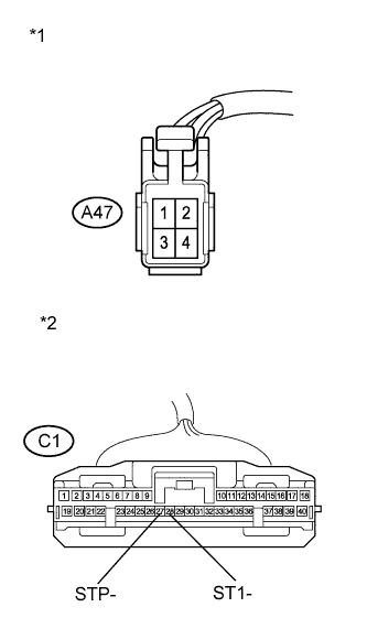
Text in Illustration *1 Front view of wire harness connector
(to Stop Light Switch Assembly)
*2 Front view of wire harness connector
(to Driving Support ECU)
Disconnect the stop light switch assembly connector.
-
Disconnect the driving support ECU connector.
-
Measure the resistance according to the value(s) in the table below.
Standard Resistance (Check for Open) Tester Connection Switch Condition Specified Condition A47-3 - C1-28 (ST1-) Always Below 1 Ω A47-1 - C1-27 (STP-) Always Below 1 Ω Standard Resistance (Check for Open) Tester Connection Switch Condition Specified Condition A47-3 or C1-28 (ST1-) - Body ground Always 10 kΩ or higher -
Reconnect the stop light switch assembly connector.
-
Reconnect the driving support ECU connector.
NG
REPAIR OR REPLACE HARNESS OR CONNECTOR (STOP LIGHT SWITCH ASSEMBLY - DRIVING SUPPORT ECU)
OK
-
-
CHECK HARNESS AND CONNECTOR
-
Disconnect the stop light switch assembly connector.
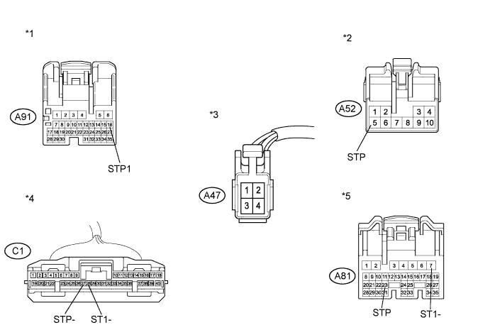
-
Disconnect the driving support ECU connector.
-
Disconnect the stop light control relay connector.
-
Disconnect the skid control ECU connector.
-
Disconnect the power management control ECU connector.
-
Measure the resistance according to the value(s) in the table below.
Standard Resistance (Check for Short) Tester Connection Switch Condition Specified Condition A47-1 or C1-27 (STP-) - Body ground Always 10 kΩ or higher A47-3 or C1-28 (ST1-) - Body ground Always 10 kΩ or higher A47-1 or A91-16 (STP1) - Body ground Always 10 kΩ or higher A47-1 or A52-5 (STP) - Body ground Always 10 kΩ or higher A47-1 or A81-23 (STP) - Body ground Always 10 kΩ or higher A47-3 or A81-7 (ST1-) - Body ground Always 10 kΩ or higher -
Reconnect the stop light switch assembly connector.
-
Reconnect the driving support ECU connector.
-
Reconnect the stop light control relay connector.
-
Reconnect the skid control ECU connector.
-
Reconnect the power management control ECU connector.
Text in Illustration *1 Front view of wire harness connector
(to Skid Control ECU)
*2 Front view of wire harness connector
(to Stop Light Control Relay)
*3 Front view of wire harness connector
(to Stop Light Switch Assembly)
*4 Front view of wire harness connector
(to Driving Support ECU)
*5 Front view of wire harness connector
(to Power Management Control ECU)
- -
NG
REPAIR OR REPLACE HARNESS OR CONNECTOR
OK
REPLACE DRIVING SUPPORT ECU Click here
-
-
CHECK HARNESS AND CONNECTOR (STOP LIGHT SWITCH ASSEMBLY - STOP LIGHT CONTROL RELAY)
-
Text in Illustration *1 Front view of wire harness connector
(to Stop Light Switch Assembly)
*2 Front view of wire harness connector
(to Stop Light Control Relay)
Disconnect the stop light switch assembly connector.
-
Disconnect the stop light control relay connector.
-
Measure the resistance according to the value(s) in the table below.
Standard Resistance (Check for Short) Tester Connection Switch Condition Specified Condition A47-2 or A52-6 (+B) - Body ground Always 10 kΩ or higher -
Reconnect the stop light switch assembly connector.
-
Reconnect the stop light control relay connector.
NG
REPAIR OR REPLACE HARNESS OR CONNECTOR (STOP LIGHT SWITCH ASSEMBLY - STOP LIGHT CONTROL RELAY)
OK
REPAIR OR REPLACE HARNESS OR CONNECTOR (STOP LIGHT SWITCH ASSEMBLY - BATTERY)
-