ДВИГАТЕЛЬ В СБОРЕ СНЯТИЕ

CAUTION / NOTICE / HINT
The necessary procedures (adjustment, calibration, initialization, or registration) that must be performed after parts are removed, installed, or replaced during the engine assembly removal/installation are shown below.
| Replacement Part or Procedure | Necessary Procedures | Effects/Inoperative when not Performed | Link |
|---|---|---|---|
| Replacement of ECM |
|
|
|
| Code registration (Immobiliser system) | Engine start function | See the Service Bulletin for the registration method. | |
| Replacement of engine assembly |
|
Engine starting | |
| Replacement of fuel supply pump assembly | Supply Pump Initialization | Engine startability | |
| Replacement of injector assembly |
|
Engine starting | |
|
Perform initialization | - | |
| Replacement of timing belt | Mode reset operation |
|
|
for A750F: |
Reset memory |
|
|
for A750F: |
ATF thermal degradation estimate reset | The value of the Data List item "ATF Thermal Degradation Estimate" is not estimated correctly | |
w/ Automatic Headlight Beam Level Control System: |
Headlight leveling ECU assembly initialization | Headlight leveling function | |
for 4WD: |
|
VSC malfunctioning |
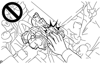
CAUTION:
To prevent burns, do not touch the engine, exhaust manifold or other high temperature components while the engine is hot.
Note
-
When replacing the parts in the following chart (A), replace the No. 1 injection pipe sub-assembly, No. 2 injection pipe sub-assembly, No. 3 injection pipe sub-assembly, No. 4 injection pipe sub-assembly and/or fuel inlet pipe sub-assembly with new ones.
Replaced Parts (A) Pipes Requiring New Replacement
-
Injector assembly (including shuffling the injector assemblies between the cylinders)
-
Common rail assembly
-
Cylinder head sub-assembly
-
No. 1 injection pipe sub-assembly
-
No. 2 injection pipe sub-assembly
-
No. 3 injection pipe sub-assembly
-
No. 4 injection pipe sub-assembly
-
Supply pump assembly
-
Common rail assembly
-
Cylinder block sub-assembly
-
Cylinder head sub-assembly
-
Cylinder head gasket
-
Timing Gear Case Assembly
Fuel inlet pipe sub-assembly -
-
After removing the No. 1 injection pipe sub-assembly, No. 2 injection pipe sub-assembly, No. 3 injection pipe sub-assembly, No. 4 injection pipe sub-assembly and fuel inlet pipe sub-assembly, clean them with a brush and compressed air.
PROCEDURE
-
PRECAUTION
Note
After turning the ignition switch off, waiting time may be required before disconnecting the cable from the battery terminal. Therefore, make sure to read the disconnecting the cable from the battery terminal notice before proceeding with work.
-
DISCONNECT CABLE FROM NEGATIVE BATTERY TERMINAL
Note
When disconnecting the cable, some systems need to be initialized after the cable is reconnected.
-
REMOVE NO. 1 ENGINE UNDER COVER ASSEMBLY
-
REMOVE NO. 2 ENGINE UNDER COVER
-
DRAIN ENGINE OIL
-
DRAIN ENGINE COOLANT
-
DRAIN MANUAL TRANSMISSION OIL (for Manual Transmission)
-
DRAIN AUTOMATIC TRANSMISSION FLUID (for Automatic Transmission)
-
DRAIN POWER STEERING FLUID
-
REMOVE HOOD SUB-ASSEMBLY
-
Disconnect the washer nozzle hose from the hood sub-assembly.
-
Remove the 4 bolts and hood sub-assembly from the 2 hood hinge assemblies.
-
-
REMOVE RADIATOR ASSEMBLY
-
REMOVE INTERCOOLER ASSEMBLY
-
REMOVE GLOVE COMPARTMENT DOOR ASSEMBLY
-
DISCONNECT ENGINE WIRE
-
Remove the ECM.
-
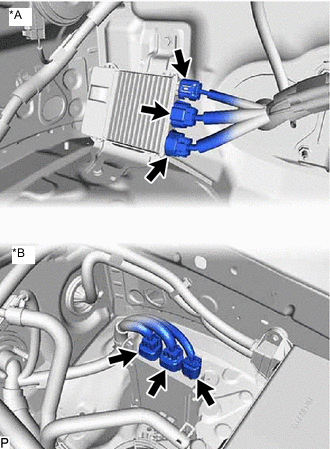
*A for LHD *B for RHD Disconnect the 3 connectors from the injector driver.
-
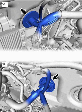
*A for LHD *B for RHD Detach the grommet and pull out the engine wire from the cabin.
-
-
REMOVE AIR CLEANER CAP AND HOSE
-
REMOVE AIR CLEANER FILTER ELEMENT SUB-ASSEMBLY
-
REMOVE AIR CLEANER CASE SUB-ASSEMBLY
-
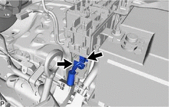
DISCONNECT WATER HOSE SUB-ASSEMBLY
-
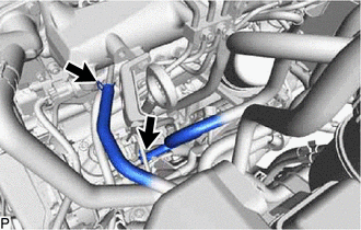
Slide the 2 clamps and disconnect the water hose sub-assembly from the water outlet and heater pipe.
-
-
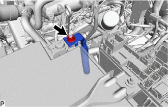
DISCONNECT FUEL HOSE
-
Slide the 2 clamps and disconnect the No. 1 fuel hose and No. 2 fuel hose from the No. 2 nozzle leakage pipe assembly and fuel supply pump assembly.
-
-
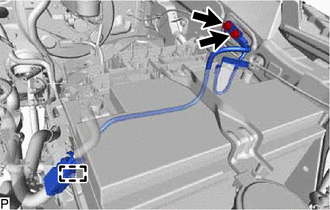
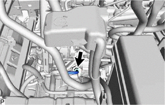
DISCONNECT UNION TO CONNECTOR TUBE HOSE
-
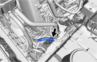
Slide the clamp and disconnect the union to connector tube hose from the No. 1 hose to hose tube.
-
-
DISCONNECT WIRE HARNESS
-
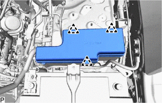
Detach the 3 clips and remove the No. 1 relay block cover upper from the engine room relay block sub-assembly.
-
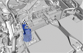
Detach the 2 clips and remove the No. 1 relay block cover side from the engine room relay block sub-assembly.
-
Remove the nut and disconnect the wire to wire from the engine room relay block sub-assembly.
-
Disconnect the 2 connectors from the engine room relay block sub-assembly.
-
Detach the clamp and remove the 2 bolts and disconnect the No. 2 engine wire.
-
Remove the nut and disconnect the engine room main wire from the battery positive cable.
-
-
REMOVE BATTERY CLAMP SUB-ASSEMBLY
-
Loosen the 2 nuts and remove the battery clamp sub-assembly from the body.
-
-
REMOVE BATTERY
-
REMOVE BATTERY TRAY
-
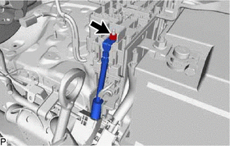
DISCONNECT PRESSURE FEED TUBE ASSEMBLY
-
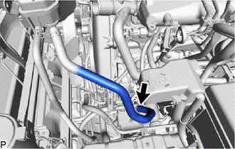
Slide the clamp and disconnect the oil reservoir to pump hose from the vane pump assembly.
-
Disconnect the pressure feed tube assembly from the vane pump assembly.
-
-
DISCONNECT COOLER COMPRESSOR ASSEMBLY
-
Remove the 4 bolts and disconnect the cooler compressor assembly from the No. 1 compressor mounting bracket.
Tech Tips
It is not necessary to completely remove the cooler compressor assembly. With the hoses connected to the cooler compressor assembly, hang the cooler compressor assembly on the vehicle body with a rope.
-
-
REMOVE FRONT EXHAUST PIPE ASSEMBLY
-
REMOVE FRONT PROPELLER SHAFT ASSEMBLY
-
REMOVE PROPELLER WITH CENTER BEARING SHAFT ASSEMBLY
-
REMOVE MANUAL TRANSMISSION UNIT ASSEMBLY (for Manual Transmission)
-
REMOVE DRIVE PLATE AND TORQUECONVERTER SETTING BOLT (for Automatic Transmission)
-
REMOVE AUTOMATIC TRANSMISSION ASSEMBLY (for Automatic Transmission)
-
REMOVE CLUTCH COVER ASSEMBLY (for Manual Transmission)
-
REMOVE CLUTCH DISC ASSEMBLY (for Manual Transmission)
-
REMOVE FLYWHEEL SUB-ASSEMBLY
-
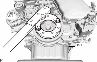
Using SST, hold the crankshaft pulley sub-assembly.
- SST
- 09213-58014 ( 91551-80840 )
- 09330-00021
-
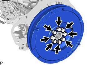
for Manual Transmission:
Remove the 8 bolts and flywheel sub-assembly from the crankshaft.
-
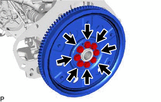
for Automatic Transmission:
Remove the 8 bolts, the rear drive plate spacer, the pump impeller drive plate and the flywheel sub-assembly from the crankshaft.
-
-
REMOVE REAR END PLATE
-
Remove the bolt and rear end plate from the cylinder block sub-assembly.
-
-
INSTALL ENGINE HANGER
-
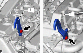
*1 No. 1 Engine Hanger Upper *2 No. 2 Engine Hanger Install the No. 1 engine hanger upper and No. 2 engine hanger with 2 bolts as shown in the illustration.
- Torque:
- for No. 1 engine hanger upper
- 25 N*m { 255 kgf*cm, 18 ft.*lbf }
- for No. 2 engine hanger
- 60 N*m { 612 kgf*cm, 44 ft.*lbf }
Tech Tips
Part No.
No. 1 engine hanger upper 12284-30020 No. 2 engine hanger 12282-67030 Bolt 90105-T0164 and 90119-T0065 Note
Install the engine hangers with new bolts.
-
-
REMOVE ENGINE ASSEMBLY
-
Attach an engine sling device and hang the engine assembly with a chain block.
-
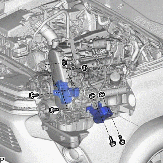
Remove the 4 bolts and 4 nuts from the body.
-
Remove the engine assembly by operating the engine sling device and chain block.
Note
-
Make sure that the engine assembly is clear of all wiring and hoses.
-
While lowering the engine assembly from the vehicle, do not allow it to contact the vehicle.
-
-
-
INSTALL ENGINE TO ENGINE STAND
Note
-
Pay attention to the angle of the sling device as the engine assembly or engine hangers may be damaged or deformed if the angle is incorrect.
-
With the exception of installing the engine assembly to an engine stand or removing the engine assembly from an engine stand, do not perform any work on the engine assembly while it is suspended, as doing so is dangerous.
-
Install the engine assembly to an engine stand with the bolts.
-
Remove the 2 bolts and No. 1 engine hanger upper and No. 2 engine hanger.
-
-
REMOVE ENGINE WIRE
-
Remove the engine wire from the engine assembly.
-
-
REMOVE FRONT ENGINE MOUNTING INSULATOR
-
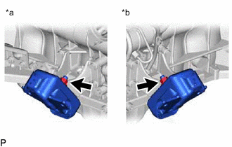
*a RH Side *b LH Side Remove the 2 nuts and 2 front engine mounting insulators from the 2 front engine mounting brackets.
-