CAN COMMUNICATION SYSTEM ECM Communication Stop Mode
DESCRIPTION
| Detection Item | Symptom | Trouble Area |
|---|---|---|
| ECM Communication Stop Mode | Either condition is met:
|
|
WIRING DIAGRAM

INSPECTION PROCEDURE
Note
Inspect the fuses for circuits related to this system before performing the following inspection procedure.
PROCEDURE
-
CHECK HARNESS AND CONNECTOR (ECM - BATTERY AND BODY GROUND)
-
for 1KD-FTV (w/ DPF)
-
Disconnect the ECM connectors.
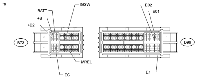
Text in Illustration *a Front view of wire harness connector
(to ECM)
- - -
Measure the resistance according to the value(s) in the table below.
Standard Resistance Tester Connection Condition Specified Condition B73-32 (EC) - Body ground Always Below 1 Ω D99-44 (E02) - Body ground Always Below 1 Ω D99-45 (E01) - Body ground Always Below 1 Ω D99-109 (E1) - Body ground Always Below 1 Ω -
Measure the voltage according to the value(s) in the table below.
Standard Voltage Tester Connection Condition Specified Condition B73-2 (BATT) - Body ground Always 11 to 14 V B73-1 (+B) - Body ground Battery positive (+) voltage applied to terminal B73-45 (MREL) 11 to 14 V B73-20 (+B2) - Body ground Battery positive (+) voltage applied to terminal B73-45 (MREL) 11 to 14 V B73-25 (IGSW) - Body ground Ignition switch ON 11 to 14 V
-
-
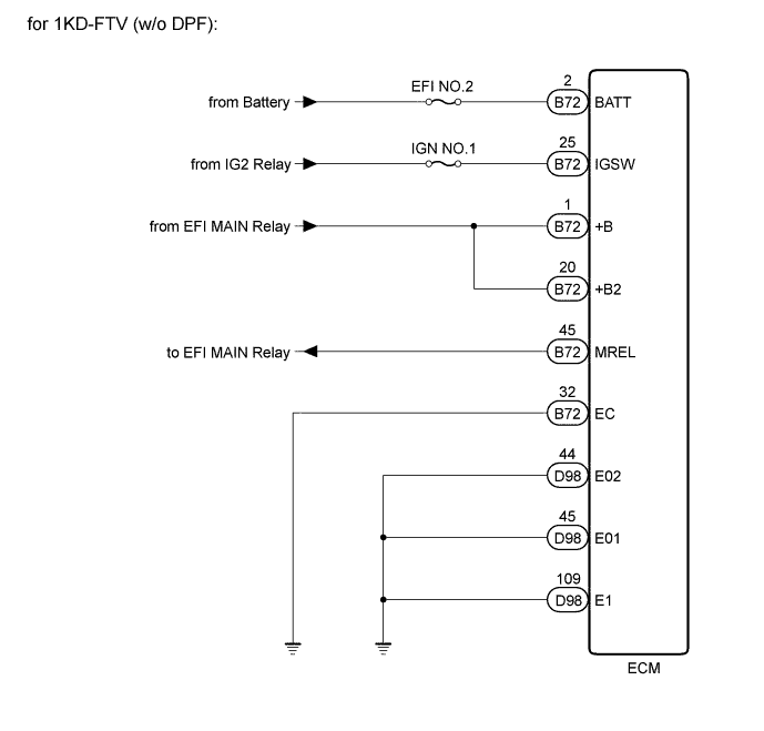
for 1KD-FTV (w/o DPF)
-
Disconnect the ECM connectors.

Text in Illustration *a Front view of wire harness connector
(to ECM)
- - -
Measure the resistance according to the value(s) in the table below.
Standard Resistance Tester Connection Condition Specified Condition B72-32 (EC) - Body ground Always Below 1 Ω D98-44 (E02) - Body ground Always Below 1 Ω D98-45 (E01) - Body ground Always Below 1 Ω D98-109 (E1) - Body ground Always Below 1 Ω -
Measure the voltage according to the value(s) in the table below.
Standard Voltage Tester Connection Condition Specified Condition B72-2 (BATT) - Body ground Always 11 to 14 V B72-1 (+B) - Body ground Battery positive (+) voltage applied to terminal B72-45 (MREL) 11 to 14 V B72-20 (+B2) - Body ground Battery positive (+) voltage applied to terminal B72-45 (MREL) 11 to 14 V B72-25 (IGSW) - Body ground Ignition switch ON 11 to 14 V
-
-
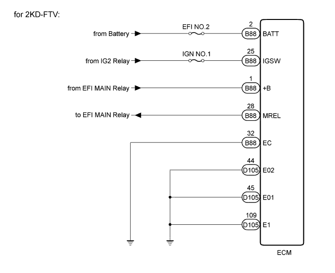
for 2KD-FTV
-
Disconnect the ECM connectors.
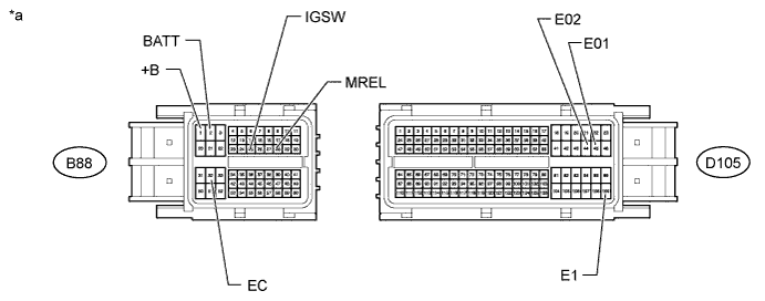
Text in Illustration *a Front view of wire harness connector
(to ECM)
- - -
Measure the resistance according to the value(s) in the table below.
Standard Resistance Tester Connection Condition Specified Condition B88-32 (EC) - Body ground Always Below 1 Ω D105-44 (E02) - Body ground Always Below 1 Ω D105-45 (E01) - Body ground Always Below 1 Ω D105-109 (E1) - Body ground Always Below 1 Ω -
Measure the voltage according to the value(s) in the table below.
Standard Voltage Tester Connection Condition Specified Condition B88-2 (BATT) - Body ground Always 11 to 14 V B88-1 (+B) - Body ground Battery positive (+) voltage applied to terminal B88-28 (MREL) 11 to 14 V B88-25 (IGSW) - Body ground Ignition switch ON 11 to 14 V
-
-
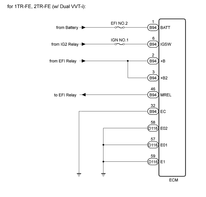
for 1TR-FE, 2TR-FE (w/ Dual VVT-i)
-
Disconnect the ECM connectors.
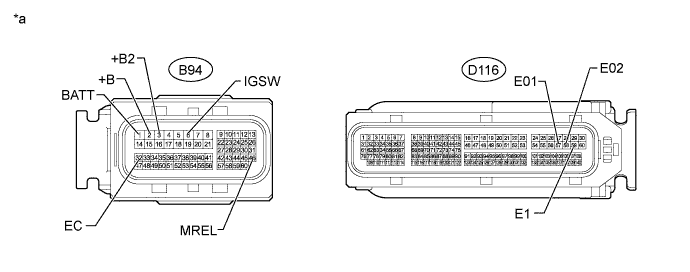
Text in Illustration *a Front view of wire harness connector
(to ECM)
- - -
Measure the resistance according to the value(s) in the table below.
Standard Resistance Tester Connection Condition Specified Condition B94-32 (EC) - Body ground Always Below 1 Ω D116-58 (E02) - Body ground Always Below 1 Ω D116-57 (E01) - Body ground Always Below 1 Ω D116-59 (E1) - Body ground Always Below 1 Ω -
Measure the voltage according to the value(s) in the table below.
Standard Voltage Tester Connection Condition Specified Condition B94-1 (BATT) - Body ground Always 11 to 14 V B94-2 (+B) - Body ground Battery positive (+) voltage applied to terminal B94-46 (MREL) 11 to 14 V B94-3 (+B2) - Body ground Battery positive (+) voltage applied to terminal B94-46 (MREL) 11 to 14 V B94-6 (IGSW) - Body ground Ignition switch ON 11 to 14 V
-
-
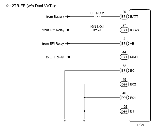
for 2TR-FE (w/o Dual VVT-i)
-
Disconnect the ECM connectors.
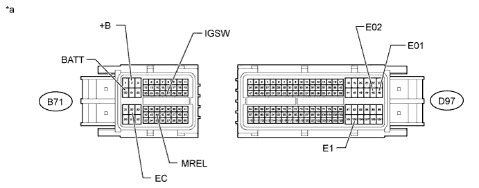
Text in Illustration *a Front view of wire harness connector
(to ECM)
- - -
Measure the resistance according to the value(s) in the table below.
Standard Resistance Tester Connection Condition Specified Condition B71-32 (EC) - Body ground Always Below 1 Ω D97-45 (E02) - Body ground Always Below 1 Ω D97-46 (E01) - Body ground Always Below 1 Ω D97-105 (E1) - Body ground Always Below 1 Ω -
Measure the voltage according to the value(s) in the table below.
Standard Voltage Tester Connection Condition Specified Condition B71-20 (BATT) - Body ground Always 11 to 14 V B71-2 (+B) - Body ground Battery positive (+) voltage applied to terminal B71-44 (MREL) 11 to 14 V B71-27 (IGSW) - Body ground Ignition switch ON 11 to 14 V
-
-
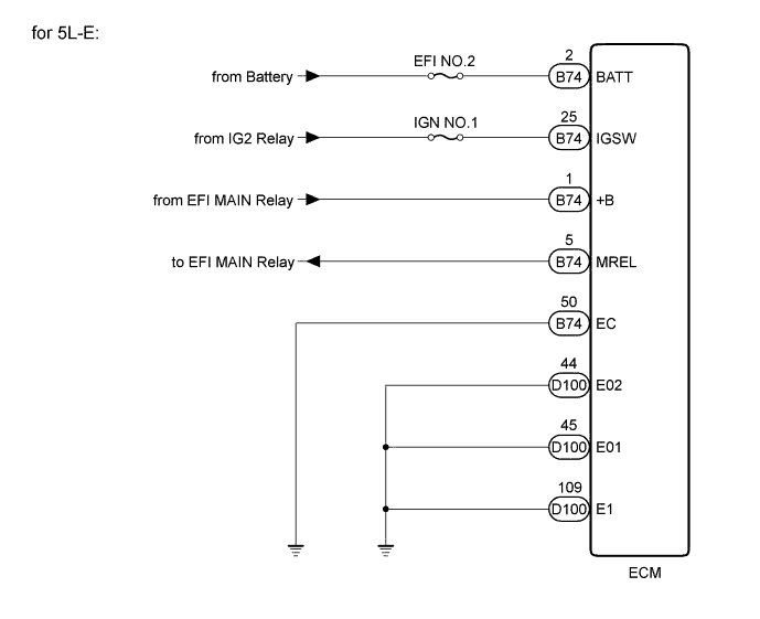
for 5L-E
-
Disconnect the ECM connectors.
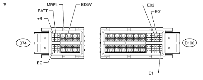
Text in Illustration *a Front view of wire harness connector
(to ECM)
- - -
Measure the resistance according to the value(s) in the table below.
Standard Resistance Tester Connection Condition Specified Condition B74-50 (EC) - Body ground Always Below 1 Ω D100-44 (E02) - Body ground Always Below 1 Ω D100-45 (E01) - Body ground Always Below 1 Ω D100-109 (E1) - Body ground Always Below 1 Ω -
Measure the voltage according to the value(s) in the table below.
Standard Voltage Tester Connection Condition Specified Condition B74-2 (BATT) - Body ground Always 11 to 14 V B74-1 (+B) - Body ground Battery positive (+) voltage applied to terminal B74-5 (MREL) 11 to 14 V B74-25 (IGSW) - Body ground Ignition switch ON 11 to 14 V
Tech Tips
*: Replacement procedure:
-
for 1KD-FTV Click here.
-
for 2KD-FTV Click here.
-
for 1TR-FE Click here.
-
for 2TR-FE (w/o Dual VVT-i) Click here.
-
for 2TR-FE (w/ Dual VVT-i) Click here.
-
for 5L-E Click here.
-
NG 
REPAIR OR REPLACE HARNESS OR CONNECTOR
OK 
REPLACE ECM*
-