REAR DOOR WINDOW FRAME MOULDING REMOVAL
CAUTION / NOTICE / HINT
The necessary procedures (adjustment, calibration, initialization or registration) that must be performed after parts are removed, installed or replaced during the rear door window frame moulding removal/installation are shown below.
| Replacement Part | Necessary Procedure | Effect/Inoperative Function When Necessary Procedures are not Performed | Link |
|---|---|---|---|
| Removal and installation of auxiliary battery terminal | Memorize steering angle neutral point | LKA/LDA system (for Mono camera type) | for Stereo Camera type: Click here for Mono Camera type: Click here |
| Lane control system (for Stereo camera type) | |||
| Parking support brake system* | |||
| Pre-collision system (for Stereo camera type) | |||
| Pre-collision system (for Mono camera type) | |||
| Adaptive high beam system | |||
Lighting system (EXT) |
|||
| Variable gear ratio steering system | |||
| Parking assist monitor system | |||
| Panoramic view monitor system | |||
| Initialize Rear Door Sunshade System | Rear door sunshade system | ||
| Initialize power trunk lid system | Power trunk lid system | ||
| Rear multiplex network door ECU LH or rear multiplex network door ECU RH is the connectors are disconnected | Initialize rear door sunshade system | The rear door sunshade system does not operate | |
|
Initialize power window control system |
|
Click here Click here
Tech Tips
-
Use the same procedure for the RH and LH sides.
-
The procedure listed below is for the LH side.
-
When removing the rear door glass sub-assembly LH, move the rear door glass sub-assembly LH to the lowest position before disconnecting the auxiliary battery negative (-) terminal.
PROCEDURE
-
PRECAUTION
Note
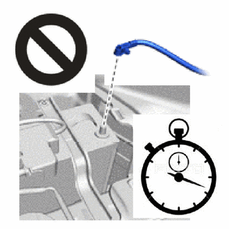
After turning the power switch off, waiting time may be required before disconnecting the cable from the negative (-) auxiliary battery terminal. Therefore, make sure to read the disconnecting the cable from the negative (-) auxiliary battery terminal notices before proceeding with work.
-
REMOVE LUGGAGE COMPARTMENT MAT SUB-ASSEMBLY
-
DISCONNECT CABLE FROM NEGATIVE AUXILIARY BATTERY TERMINAL
CAUTION:
-
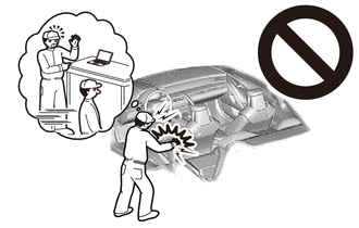
Wait at least 90 seconds after disconnecting the cable from the negative (-) auxiliary battery terminal to disable the SRS system.
-
If the airbag deploys for any reason, it may cause a serious accident.
Note
When disconnecting the cable, some systems need to be initialized after the cable is reconnected.
-
-
REMOVE REAR DOOR TRIM UPPER COVER LH
-
REMOVE REAR DOOR ARMREST COVER LH
-
REMOVE REAR DOOR NO. 2 ARMREST COVER LH
-
REMOVE REAR DOOR TRIM BOARD SUB-ASSEMBLY LH
-
REMOVE REAR DOOR TRIM COVER LH
-
REMOVE REAR DOOR NO. 2 FRAME GARNISH LH
-
REMOVE REAR DOOR FRAME GARNISH LH
-
REMOVE CURTAIN RAIL SIDE COVER LH (w/ Rear Door Sunshade)
-
REMOVE REAR CURTAIN SUB-ASSEMBLY LH (w/ Rear Door Sunshade)
-
REMOVE REAR SIDE WINDOW COVER LH (w/ Rear Door Sunshade)
-
REMOVE REAR DOOR GLASS INNER WEATHERSTRIP LH
-
REMOVE REAR MULTIPLEX NETWORK DOOR ECU LH
-
REMOVE REAR DOOR SERVICE HOLE COVER LH
-
REMOVE REAR DOOR FRONT BELT MOULDING END COVER LH
-
REMOVE REAR DOOR REAR BELT MOULDING END COVER LH
-
REMOVE REAR DOOR NO. 2 WEATHERSTRIP LH
-
REMOVE REAR DOOR WINDOW FRAME MOULDING LH(CENTER PILLAR SIDE)
-
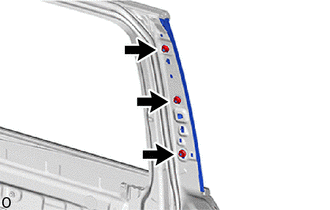
Remove the 3 nuts.
-

Protective Tape Put protective tape around the rear door window frame moulding LH (center pillar side).
-
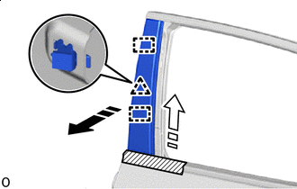

Remove in this Direction (1) 
Remove in this Direction (2) Detach the clip and guide and remove the rear door window frame moulding LH (center pillar side) as shown in the illustration.
-
-
REMOVE REAR DOOR FRONT GLASS RUN LH
-
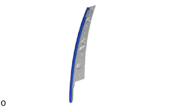
Remove the rear door front glass run LH.
-
-
REMOVE REAR DOOR WINDOW FRAME MOULDING LH(REAR PILLAR SIDE)
Tech Tips
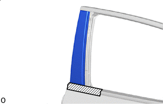
When removing the rear door window frame moulding LH (rear pillar side), heat the vehicle body and rear door window frame moulding sub-assembly (rear pillar side) using a heat light.
Standard Item Temperature Vehicle Body 40 to 60°C (104 to 140°F) Rear Door Window Frame Moulding LH (Rear Pillar Side) 20 to 30°C (68 to 86°F)
-
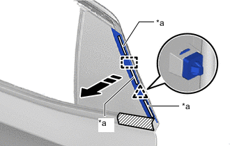
*a Double-sided tape Remove in this Direction Detach the clip, guide and double-sided tape and remove the rear door window frame moulding LH (rear pillar side) as shown in the illustration.
-
-
REMOVE REAR DOOR OUTSIDE MOULDING INSERT LH
-
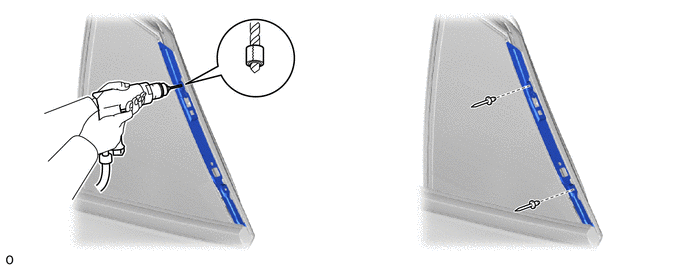
Insert a 4.0 mm (0.157 in.) drill bit into a drill.
-
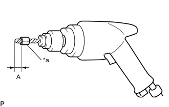
*a Tape Tape the 4.0 mm (0.157 in.) drill bit 5.0 mm (0.197 in.) from the tip as shown in the illustration.
Standard Measurement Area Measurement A 5.0 mm (0.197 in.) Note
Tape the 4.0 mm (0.157 in.) drill bit to prevent the drill bit from going too deep.
-
Lightly press the drill against the rivets to drill off the rivet flanges, and remove the 2 rivets.
CAUTION:
Be careful of the drilled rivets, as they may be hot.
Note
-
Pressing the drill too firmly will cause the rivet to turn and result in the rivet not being drilled through.
-
Prying the rivets with the drill may damage the rivet installation holes or drill bit.
-
-
Using a vacuum cleaner, remove the rivet fragments and shavings from the drilled areas.
-
Remove the rear door outside moulding insert LH.
-
-
REMOVE REAR DOOR BELT MOULDING LH
-
REMOVE REAR DOOR QUARTER WINDOW GLASS SUB-ASSEMBLY LH
-
REMOVE REAR DOOR GLASS RUN LH
-
REMOVE REAR DOOR GLASS SUB-ASSEMBLY LH
-
REMOVE REAR DOOR FRONT WINDOW GUIDE SUB-ASSEMBLY LH
-
REMOVE REAR DOOR REAR WINDOW FRAME LH
-
REMOVE REAR DOOR BELT MOULDING SUB-ASSEMBLY LH
-
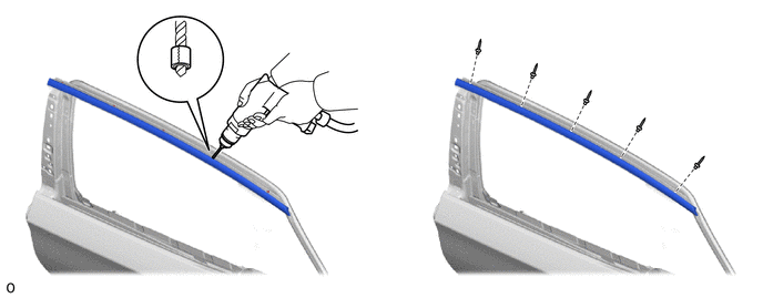
Insert a 4.0 mm (0.157 in.) drill bit into a drill.
-
*a Tape Tape the 4.0 mm (0.157 in.) drill bit 5.0 mm (0.197 in.) from the tip as shown in the illustration.
Standard Measurement Area Measurement A 5.0 mm (0.197 in.) Note
Tape the 4.0 mm (0.157 in.) drill bit to prevent the drill bit from going too deep.
-
Lightly press the drill against the rivets to drill off the rivet flanges, and remove the 5 rivets.
CAUTION:
Be careful of the drilled rivets, as they may be hot.
Note
-
Pressing the drill too firmly will cause the rivet to turn and result in the rivet not being drilled through.
-
Prying the rivets with the drill may damage the rivet installation holes or drill bit.
-
-
Using a vacuum cleaner, remove the rivet fragments and shavings from the drilled areas.
-
Remove the rear door belt moulding sub-assembly LH.
-
-
REMOVE REAR DOOR NO. 3 GLASS RUN LH
-
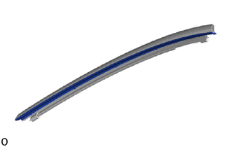
Remove the rear door No. 3 glass run LH.
-
-
REMOVE REAR DOOR UPPER WINDOW FRAME MOULDING LH
-
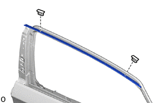
Remove the 2 clips and the rear door upper window frame moulding LH.
-