CAUTION / NOTICE / HINT
The necessary procedures (adjustment, calibration, initialization or registration) that must be performed after parts are removed, installed or replaced during the spiral with sensor cable sub-assembly removal/installation are shown below.
| Replacement Part or Procedure | Necessary Procedures | Effects / Inoperative when not Performed | Link |
|---|---|---|---|
| Disconnect cable from negative (-) auxiliary battery terminal | Memorize steering angle neutral point | LKA/LDA system (for Mono camera type) | for Mono Camera type: for Stereo Camera type: |
| Lane control system (for Stereo camera type) | |||
| Parking support brake system* | |||
| Pre-collision system (for Mono camera type) | |||
| Pre-collision system (for Stereo camera type) | |||
| Adaptive high beam system | |||
|
|||
| Variable gear ratio steering system | |||
| Parking assist monitor system | |||
| Panoramic View Monitor System | |||
| Initialize rear door sunshade system | Rear door sunshade system | ||
| Initialize power trunk lid system | Power trunk lid system | ||
| Steering sensor (Including removal and installation) | Steering angle neutral point | Parking support brake system | |
| Parking assist monitor system | |||
| Panoramic view monitor system | |||
| Steering angle setting | Parking assist monitor system | ||
| Panoramic view monitor system |
-
Use the same procedure for RHD and LHD vehicles.
-
The procedure listed below is for LHD vehicles.
PROCEDURE
- Click here
PRECAUTION
CAUTION:Note:After turning the power switch off, waiting time may be required before disconnecting the cable from the negative (-) auxiliary battery terminal. Therefore, make sure to read the disconnecting the cable from the negative (-) auxiliary battery terminal notices before proceeding with work.
- Click here
PLACE FRONT WHEELS FACING STRAIGHT AHEAD
- Click here
CUSTOMIZE POWER TILT AND POWER TELESCOPIC STEERING COLUMN SYSTEM
- Click here
REMOVE LUGGAGE COMPARTMENT MAT SUB-ASSEMBLY
- Click here
DISCONNECT CABLE FROM NEGATIVE AUXILIARY BATTERY TERMINAL
CAUTION: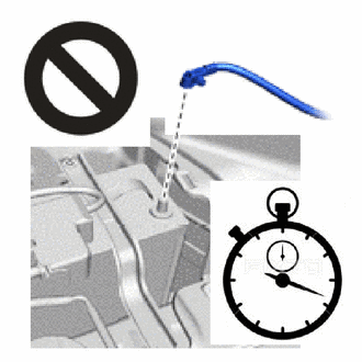
-
Wait at least 90 seconds after disconnecting the cable from the negative (-) auxiliary battery terminal to disable the SRS system.
-
If the airbag deploys for any reason, it may cause a serious accident.
Note:When disconnecting the cable, some systems need to be initialized after the cable is reconnected.
-
- Click here
REMOVE STEERING WHEEL ASSEMBLY
- Click here
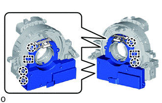
INSPECT SPIRAL WITH SENSOR CABLE SUB-ASSEMBLY
-
Check that the front wheels are facing straight ahead.
-
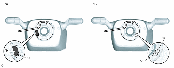
*A Colored Roller (Visible Type) *B Flat Cable (Visible Type) *a Check Window *b Colored Roller *c Top of Flat Cable U-turn - - Check that the spiral with sensor cable sub-assembly is center position.
OK The connector is at the top. The colored roller or the top of the flat cable U-turn can be checked from the check window. Note:If the result is not as specified, it is possible that the spiral cable sub-assembly is broken. Replace the spiral cable sub-assembly with a new one.
-
- Click here
REMOVE LOWER STEERING COLUMN COVER
- Click here
REMOVE UPPER STEERING COLUMN COVER
- Click here
REMOVE SPIRAL WITH SENSOR CABLE SUB-ASSEMBLY
Note:
-
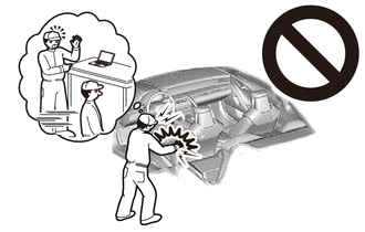
Do not replace the spiral with sensor cable sub-assembly with the battery connected and the power switch on (IG).
-
Do not rotate the spiral with sensor cable sub-assembly with the battery connected and the power switch on (IG).
-
When rotating the spiral with sensor cable sub-assembly to check the operation of the spiral with sensor cable sub-assembly (checking for abnormal noise, checking the Data List, etc.), make sure to perform the inspection with the steering wheel assembly installed.
-
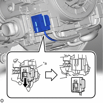
*a Slider 
Slide in this Direction Slide the slider to release the lock, and then disconnect the airbag connector.
Note:When disconnecting any airbag connector, take care not to damage the airbag wire harness.
-
Disconnect each connector.
-
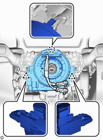
Detach the claw and clip to remove the spiral with sensor cable sub-assembly.
-
- Click here
REMOVE STEERING SENSOR
Note:
-
Remove the steering sensor from the spiral cable sub-assembly only when replacing the spiral cable sub-assembly.
-
Removing the steering sensor from the spiral cable sub-assembly without using a lock pin may result in a misaligned center position of the steering sensor. Therefore, make sure to use the lock pin provided with a new spiral cable when removing the steering sensor from the spiral cable sub-assembly.
-
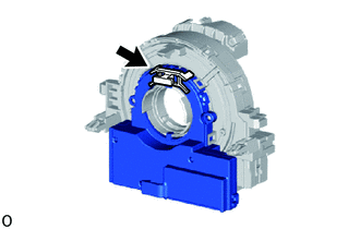
Install the lock pin to the steering sensor.
Note:
-
Use the lock pin provided with a new spiral cable.
-
Do not remove the lock pin before the spiral cable is installed to the steering sensor.
-
-
Detach the claw and guide to remove the steering sensor from the spiral cable sub-assembly.
-