CAUTION / NOTICE / HINT
The necessary procedures (adjustment, calibration, initialization, or registration) that must be performed after parts are removed, installed, or replaced during the front door lock assembly removal/installation are shown below.
| Replacement Part | Necessary Procedure | Effect/Inoperative Function When Necessary Procedures are not Performed | Link |
|---|---|---|---|
| Removal and installation of auxiliary battery terminal | Memorize steering angle neutral point | LKA/LDA system (for Mono camera type) | for Stereo Camera type:Click here for Mono Camera type:Click here |
| Lane control system (for Stereo camera type) | |||
| Parking support brake system* | |||
| Pre-collision system (for Stereo camera type) | |||
| Pre-collision system (for Mono camera type) | |||
| Adaptive high beam system | |||
|
|||
| Variable gear ratio steering system | |||
| Parking assist monitor system | |||
| Panoramic view monitor system | |||
| Initialize Rear Door Sunshade System | Rear door sunshade system | ||
| Initialize power trunk lid system | Power trunk lid system | ||
|
Side television camera view adjustment | Panoramic view monitor system | |
|
Initialize power window control system |
|
-
Use the same procedure for RHD and LHD vehicles.
-
The procedure listed below is for LHD vehicles.
-
Use the same procedure for the RH and LH sides.
-
The procedure listed below is for the LH side.
-
When removing the front door glass sub-assembly LH, move the front door glass sub-assembly LH to the lowest position before disconnecting the auxiliary battery negative (-) terminal.
PROCEDURE
- Click here
PRECAUTION
CAUTION:Note:After turning the power switch off, waiting time may be required before disconnecting the cable from the negative (-) auxiliary battery terminal. Therefore, make sure to read the disconnecting the cable from the negative (-) auxiliary battery terminal notices before proceeding with work.
- Click here
REMOVE LUGGAGE COMPARTMENT MAT SUB-ASSEMBLY
- Click here
DISCONNECT CABLE FROM NEGATIVE AUXILIARY BATTERY TERMINAL
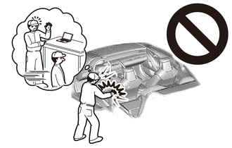
CAUTION: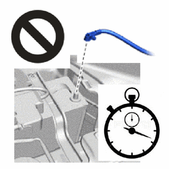
-
Wait at least 90 seconds after disconnecting the cable from the negative(-) auxiliary battery terminal to disable the SRS system.
-
If the airbag deploys for any reason, it may cause a serious accident.
Note:When disconnecting the cable, some systems need to be initialized after the cable is reconnected.
-
- Click here
REMOVE FRONT DOOR TRIM UPPER COVER LH
- Click here
REMOVE FRONT DOOR ARMREST COVER LH
- Click here
REMOVE FRONT DOOR NO. 2 ARMREST COVER LH
- Click here
REMOVE FRONT DOOR TRIM BOARD SUB-ASSEMBLY LH
- Click here
REMOVE FRONT DOOR TRIM COVER LH
- Click here
REMOVE UPPER DOOR FRAME GARNISH LH
- Click here
REMOVE FRONT DOOR GLASS INNER WEATHERSTRIP LH
- Click here
REMOVE FRONT DOOR VENT SEAL LH
- Click here
REMOVE FRONT DOOR PANEL PROTECTOR LH
- Click here
REMOVE FRONT NO. 1 SPEAKER ASSEMBLY
- Click here
REMOVE FRONT DOOR SERVICE HOLE COVER LH
- Click here
REMOVE OUTER MIRROR INSTALL HOLE COVER LH
- Click here
REMOVE FRONT MULTIPLEX NETWORK DOOR ECU LH
- Click here
REMOVE OUTER REAR VIEW MIRROR ASSEMBLY LH
- Click here
REMOVE DOOR SIDE AIRBAG SENSOR LH
- Click here
REMOVE FRONT DOOR ARMREST SET BRACKET LH
- Click here
REMOVE FRONT DOOR NO. 3 WEATHERSTRIP LH
- Click here
REMOVE FRONT DOOR NO. 2 WEATHERSTRIP LH
- Click here
REMOVE FRONT DOOR BELT MOULDING LH
- Click here
REMOVE FRONT DOOR REAR BELT MOULDING END COVER LH
- Click here
REMOVE FRONT DOOR WINDOW FRAME MOULDING LH(CENTER PILLAR SIDE)
- Click here
REMOVE FRONT PILLAR UPPER COVER SUB-ASSEMBLY LH
- Click here
REMOVE FRONT DOOR GLASS RUN LH
- Click here
REMOVE FRONT DOOR FRONT GLASS RUN LH
- Click here
REMOVE FRONT DOOR GLASS SUB-ASSEMBLY LH
- Click here
REMOVE FRONT DOOR REAR LOWER FRAME SUB-ASSEMBLY LH
- Click here
REMOVE FRONT DOOR NO. 2 GLASS RUN LH
- Click here
REMOVE FRONT DOOR REAR WINDOW FRAME LH
- Click here
REMOVE FRONT DOOR UPPER WINDOW FRAME MOULDING LH
- Click here
REMOVE FRONT DOOR FRONT WINDOW FRAME MOULDING LH
- Click here
REMOVE FRONT DOOR WINDOW REGULATOR ASSEMBLY LH
- Click here
REMOVE FRONT DOOR OUTSIDE HANDLE ASSEMBLY LH (for Driver Side)
- Click here
REMOVE FRONT DOOR LOCK CYLINDER ASSEMBLY LH (for Driver Side)
- Click here
REMOVE FRONT DOOR LOCK WITH MOTOR ASSEMBLY LH
-
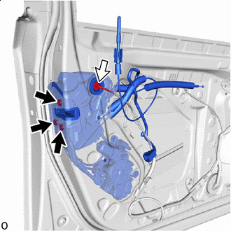

"TORX" screw 
Connector Disconnect the connector.
-
Using a T30 "TORX" socket wrench, remove the 3 TORX screws.
-

Remove in this Direction Remove the 2 bolts and front door lock with motor assembly LH in the direction indicated by the arrow shown in the illustration.
Note:Do not damage the vehicle body with front door lock with motor assembly LH.
Tip:Remove the front door lock with motor assembly LH while supporting it with one hand.
-
When reusing front door lock with motor assembly LH:
-
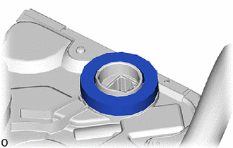
Remove the door lock wire harness seal from the front door lock with motor assembly LH.
-
-
- Click here
REMOVE FRONT DOOR LOCK COVER SUB-ASSEMBLY LH
-
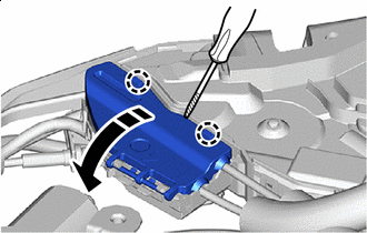
Remove in this Direction 
Protective Tape Using a thin-bladed screwdriver, detach the claw and open the front door lock cover sub-assembly LH.
-
Detach the claw and remove the front door lock cover sub-assembly LH.
-
- Click here
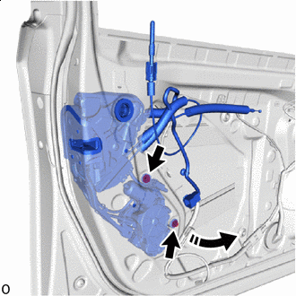
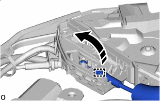
REMOVE FRONT DOOR LOCK REMOTE CONTROL CABLE ASSEMBLY LH
-
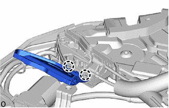
Remove in this Direction As shown in the illustration, detach the clamp and remove the front door lock remote control cable assembly LH.
-
- Click here
REMOVE FRONT DOOR INSIDE LOCKING CABLE ASSEMBLY LH
-
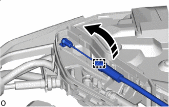
Remove in this Direction As shown in the illustration, detach the clamp and remove the front door inside locking cable assembly LH.
-