STEERING CONTROL ECU REMOVAL
CAUTION / NOTICE / HINT
The necessary procedures (adjustment, calibration, initialization, or registration) that must be performed after parts are removed, installed, or replaced during the front steering control ECU removal/installation are shown below.
| Replacement Part or Procedure | Necessary Procedure | Effect/Inoperative when not Performed | Link |
|---|---|---|---|
| Disconnect cable from negative auxiliary battery terminal | Memorize steering angle neutral point | LKA/LDA system (for Mono camera type) | for Stereo Camera type: Click here for Mono Camera type: Click here |
| Lane control system (for Stereo camera type) | |||
| Parking support brake system* | |||
| Pre-collision system (for Mono camera type) | |||
| Pre-collision system (for Stereo camera type) | |||
| Adaptive high beam system | |||
Lighting system (EXT) |
|||
| Variable gear ratio steering system | |||
| Parking assist monitor system | |||
| Panoramic view monitor system | |||
| Initialize rear door sunshade system | Rear door sunshade system | ||
| Initialize power trunk lid system | Power trunk lid system | ||
| VGRS ECU (front steering control ECU) | Perform actuator angle neutral point calibration and initialization |
|
Click here Click here
Tech Tips
-
Use the same procedure for RHD and LHD vehicles.
-
The procedure listed below is for LHD vehicles.
PROCEDURE
-
PRECAUTION
Note
After turning the power switch off, waiting time may be required before disconnecting the cable from the negative (-) auxiliary battery terminal. Therefore, make sure to read the disconnecting the cable from the negative (-) auxiliary battery terminal notices before proceeding with work.
-
REMOVE LUGGAGE COMPARTMENT MAT SUB-ASSEMBLY
-
DISCONNECT CABLE FROM NEGATIVE AUXILIARY BATTERY TERMINAL
Note
When disconnecting the cable, some systems need to be initialized after the cable is reconnected.
-
REMOVE LOWER NO. 2 INSTRUMENT PANEL AIRBAG ASSEMBLY
-
REMOVE INSTRUMENT SIDE PANEL LH
-
REMOVE LOWER NO. 1 INSTRUMENT PANEL PAD SUB-ASSEMBLY
-
REMOVE LOWER INSTRUMENT PANEL FINISH PANEL ASSEMBLY
-
REMOVE GLOVE COMPARTMENT DOOR PAD PLATE
-
REMOVE GLOVE COMPARTMENT DOOR ASSEMBLY
-
REMOVE FRONT STEERING CONTROL ECU
-
Fold back the floor carpet.
-
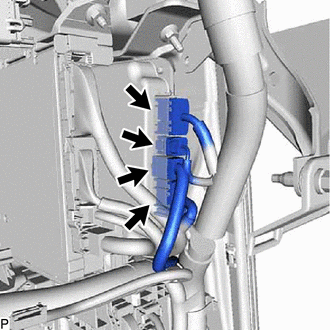
Disconnect the 4 connectors from the front steering control ECU.
-
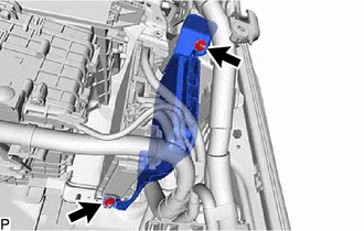
Remove the 2 nuts and front steering control ECU.
-