CAUTION / NOTICE / HINT
-
Use the same procedure for the RH and LH side.
-
The following procedure is for the LH side.
PROCEDURE
- Click here
INSTALL FRONT UPPER NO. 1 SUSPENSION ARM ASSEMBLY LH (for 2WD)
-
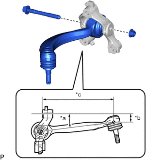
*a 3.67° *b 40.7 mm (1.60 in.) *c 226.9 mm (8.93 in.) Temporarily install the front upper No. 1 suspension arm assembly LH to the front upper No. 1 arm bracket LH with the bolt and nut.
Tip:When installing the front upper No. 1 suspension arm assembly LH, temporarily tighten the bolts at the position shown in the illustration.
-
Fully tighten the bolt.
45 N*m 459 kgf*cm 33 ft.*lbf
-
- Click here
INSTALL FRONT UPPER NO. 2 SUSPENSION ARM ASSEMBLY LH (for 2WD)
-
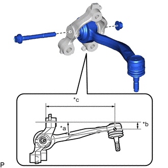
*a 5.33° *b 35.4 mm (1.39 in.) *c 211 mm (8.31 in.) Temporarily install the front upper No. 2 suspension arm assembly LH to the front upper No. 2 arm bracket LH with the bolt and nut.
Tip:When installing the front upper No. 2 suspension arm assembly LH, temporarily tighten the bolts at the position shown in the illustration.
-
Fully tighten the bolt.
45 N*m 459 kgf*cm 33 ft.*lbf
-
- Click here
INSTALL FRONT UPPER NO. 1 SUSPENSION ARM ASSEMBLY LH (for AWD)
-
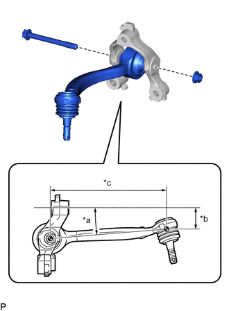
*a 4.84° *b 40.1 mm (1.58 in.) *c 215.3 mm (8.48 in.) Temporarily install the front upper No. 1 suspension arm assembly LH to the front upper No. 1 arm bracket LH with the bolt and nut.
Tip:When installing the front upper No. 1 suspension arm assembly LH, temporarily tighten the bolts at the position shown in the illustration.
-
Fully tighten the bolt.
45 N*m 459 kgf*cm 33 ft.*lbf
-
- Click here
INSTALL FRONT UPPER NO. 2 SUSPENSION ARM ASSEMBLY LH (for AWD)
-
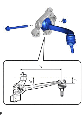
*a 7.34° *b 30.8 mm (1.21 in.) *c 210.7 mm (8.30 in.) Temporarily install the front upper No. 2 suspension arm assembly LH to the front upper No. 2 arm bracket LH with the bolt and nut.
Tip:When installing the front upper No. 2 suspension arm assembly LH, temporarily tighten the bolts at the position shown in the illustration.
-
Fully tighten the bolt.
45 N*m 459 kgf*cm 33 ft.*lbf
-
- Click here
INSTALL FRONT UPPER NO. 1 ARM BRACKET LH (for 2WD)
-
*a Torque Wrench Fulcrum Length w/ Air Suspension
-
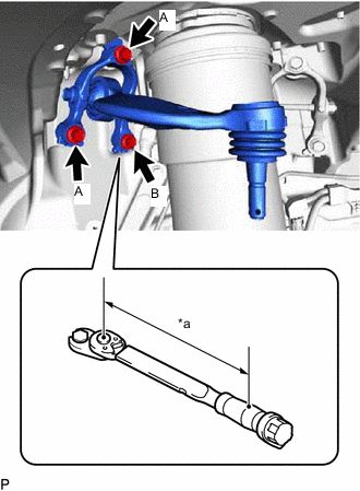
Install the front upper No. 1 arm bracket LH with the 2 bolts (A).
40 N*m 408 kgf*cm 30 ft.*lbf -
Using a 14 mm union nut wrench,, install the bolt (B).
Specified tightening torque 40 N*m 408 kgf*cm 30 ft.*lbf Tip:
-
Calculate the torque wrench reading when changing the fulcrum length of the torque wrench.
-
When using a union nut wrench (fulcrum length of 25 mm (0.984 in.)) + torque wrench (fulcrum length of 180 mm (7.087 in.)): 35.1 N*m (358 kgf*cm, 26 ft.*lbf)
-
-
-
w/o Air Suspension
-
Install the front upper No. 1 arm bracket LH with the 3 bolts.
40 N*m 408 kgf*cm 30 ft.*lbf
-
-
- Click here
INSTALL FRONT UPPER NO. 2 ARM BRACKET LH (for 2WD)
-
*a Torque Wrench Fulcrum Length w/ Air Suspension
-
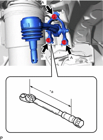
Install the front upper No. 2 arm bracket LH with the 2 bolts (A).
40 N*m 408 kgf*cm 30 ft.*lbf -
Using a 14 mm union nut wrench,, install the bolt (B).
Specified tightening torque 40 N*m 408 kgf*cm 30 ft.*lbf Tip:
-
Calculate the torque wrench reading when changing the fulcrum length of the torque wrench.
-
When using a union nut wrench (fulcrum length of 25 mm (0.984 in.)) + torque wrench (fulcrum length of 180 mm (7.087 in.)): 35.1 N*m (358 kgf*cm, 26 ft.*lbf)
-
-
-
w/o Air Suspension
-
Install the front upper No. 2 arm bracket LH with the 3 bolts.
40 N*m 408 kgf*cm 30 ft.*lbf
-
-
- Click here
INSTALL FRONT UPPER NO. 1 ARM BRACKET LH (for AWD)
-
w/ Air Suspension
-
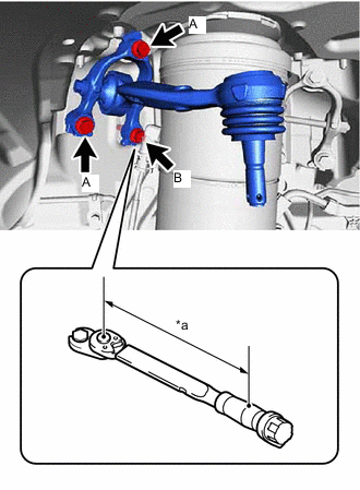
*a Torque Wrench Fulcrum Length Install the front upper No. 1 arm bracket LH with the 2 bolts (A).
40 N*m 408 kgf*cm 30 ft.*lbf -
Using a 14 mm union nut wrench,, install the bolt (B).
Specified tightening torque 40 N*m 408 kgf*cm 30 ft.*lbf Tip:
-
Calculate the torque wrench reading when changing the fulcrum length of the torque wrench.
-
When using a union nut wrench (fulcrum length of 25 mm (0.984 in.)) + torque wrench (fulcrum length of 180 mm (7.087 in.)): 35.1 N*m (358 kgf*cm, 26 ft.*lbf)
-
-
-
w/o Air Suspension
-
Install the front upper No. 1 arm bracket LH with the 3 bolts.
40 N*m 408 kgf*cm 30 ft.*lbf
-
-
- Click here
INSTALL FRONT UPPER NO. 2 ARM BRACKET LH (for AWD)
-
w/ Air Suspension
-
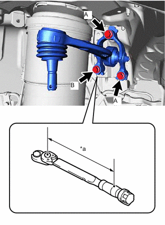
*a Torque Wrench Fulcrum Length Install the front upper No. 2 arm bracket LH with the 2 bolts (A).
40 N*m 408 kgf*cm 30 ft.*lbf -
Using a 14 mm union nut wrench,, install the bolt (B).
Specified tightening torque 40 N*m 408 kgf*cm 30 ft.*lbf Tip:
-
Calculate the torque wrench reading when changing the fulcrum length of the torque wrench.
-
When using a union nut wrench (fulcrum length of 25 mm (0.984 in.)) + torque wrench (fulcrum length of 180 mm (7.087 in.)): 35.1 N*m (358 kgf*cm, 26 ft.*lbf)
-
-
-
w/o Air Suspension
-
Install the front upper No. 2 arm bracket LH with the 3 bolts.
40 N*m 408 kgf*cm 30 ft.*lbf
-
-
- Click here
CONNECT STEERING KNUCKLE ASSEMBLY LH (for 2WD)
-
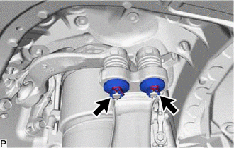
Install the steering knuckle assembly LH to the front upper No. 1 suspension arm assembly LH and front upper No. 2 suspension arm assembly LH with the 2 nuts.
60 N*m 612 kgf*cm 44 ft.*lbf -
Install 2 new clips.
Note:Further tighten the nut up to 60° if the holes for the clip are not aligned.
-
- Click here
CONNECT STEERING KNUCKLE ASSEMBLY LH (for AWD)
-
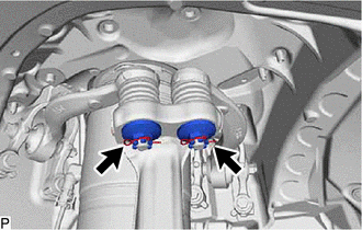
Install the steering knuckle assembly LH to the front upper No. 1 suspension arm assembly LH and front upper No. 2 suspension arm assembly LH with the 2 nuts.
60 N*m 612 kgf*cm 44 ft.*lbf -
Install 2 new clips.
Note:Further tighten the nut up to 60° if the holes for the clip are not aligned.
-
- Click here
INSTALL FRONT WHEEL
- Click here
INSPECT AND ADJUST FRONT WHEEL ALIGNMENT
-
for 2WD:
-
for AWD:
-
- Click here
INSPECT AND ADJUST VEHICLE HEIGHT (w/ Air Suspension)
- Click here
PERFORM INITIALIZATION
Parking support brake system Panoramic view monitor system Parking assist monitor system
- w/o Air Suspension System:
-
Automatic headlight beam level control system
- Click here
ADJUST HEADLIGHT AIMING