REAR AIR CONDITIONING UNIT REMOVAL
CAUTION / NOTICE / HINT
The necessary procedures (adjustment, calibration, initialization or registration) that must be performed after parts are removed, installed or replaced during the rear cooling unit assembly removal/installation are shown below.
| Replacement Part or Procedure | Necessary Procedures | Effects / Inoperative when not Performed | Link |
|---|---|---|---|
| Disconnect cable from negative auxiliary battery terminal | Memorize steering angle neutral point | LKA/LDA system (for Mono camera type) | for Stereo Camera type: Click here for Mono Camera type: Click here |
| Lane control system (for Stereo camera type) | |||
| Parking support brake system* | |||
| Pre-collision system (for Mono camera type) | |||
| Pre-collision system (for Stereo camera type) | |||
| Adaptive high beam system | |||
Lighting system (EXT) |
|||
| Variable gear ratio steering system | |||
| Parking assist monitor system | |||
| Panoramic view monitor system | |||
| Initialize rear door sunshade system | Rear door sunshade system | ||
| Initialize power trunk lid system | Power trunk lid system | ||
| Steering sensor (Including removal and installation) | Steering angle neutral point | Parking support brake system | |
| Parking assist monitor system | |||
| Panoramic view monitor system | |||
| Steering angle setting | Parking assist monitor system | ||
| Panoramic view monitor system |
Click here Click here
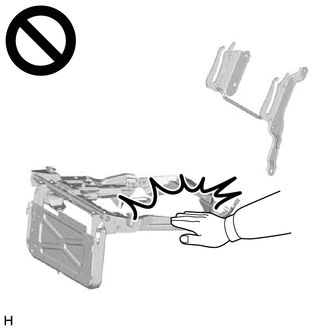
CAUTION:
-
Wear protective gloves. Sharp areas on the parts may injure your hands.
-
There is risk of injury.
Note
-
If the rear seat cushion airbag assembly LH was deployed, replace the rear seat cushion panel LH, rear seat cushion pad and separate type rear seat cushion cover with the necessary parts in accordance with the extent of the collision damage.
-
If the rear seat airbag assembly LH was deployed, replace the rear seat sub panel sub-assembly LH, separate type rear seatback pad and separate type rear seatback cover with the necessary parts in accordance with the extent of the collision damage.
-
Replace any other damaged parts as necessary.
Tech Tips
-
Use the same procedure as for the LHD and RHD vehicles.
-
The procedure listed below is for the LHD vehicles.
PROCEDURE
-
PRECAUTION
CAUTION:
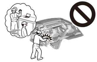
Some of these service operations affect the SRS airbag system. Read the precautionary notices concerning the SRS airbag system before servicing.
Note
After turning the power switch off, waiting time may be required before disconnecting the cable from the negative (-) auxiliary battery terminal. Therefore, make sure to read the disconnecting the cable from the negative (-) auxiliary battery terminal notices before proceeding with work.
-
REMOVE LUGGAGE COMPARTMENT MAT SUB-ASSEMBLY
-
DISCONNECT CABLE FROM NEGATIVE AUXILIARY BATTERY TERMINAL
CAUTION:
-
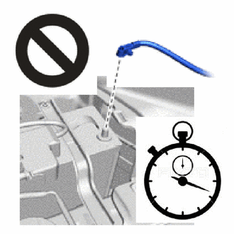
Wait at least 90 seconds after disconnecting the cable from the negative (-) auxiliary battery terminal to disable the SRS system.
-
SRS parts are equipped with a backup power source. If work is started within 90 seconds of turning the power switch off and disconnecting the cable from the negative (-) auxiliary battery terminal, SRS parts may deploy.
Note
When disconnecting the cable, some systems need to be initialized after the cable is reconnected.
-
-
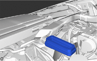
DRAIN REFRIGERANT LINE
-
for HFC-134a(R134a):
-
-
REMOVE REAR SEAT ASSEMBLY
-
for Fixed Seat Type:
-
for Power Seat:
-
-
REMOVE PACKAGE TRAY TRIM PANEL ASSEMBLY (for Fixed Seat Type)
-
REMOVE PACKAGE TRAY TRIM PANEL ASSEMBLY (for Power Seat)
-
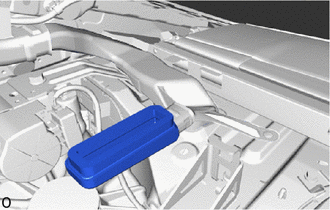
REMOVE NO. 4 REAR AIR DUCT
-
Remove the No. 4 rear air duct.
-
-
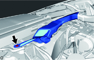
REMOVE NO. 5 REAR AIR DUCT
-
Remove the No. 5 rear air duct.
-
-
REMOVE NO. 2 ROOF SIDE AIR DUCT LH
-
Using a clip remover, detach the clip and pull the No. 2 roof side air duct LH out from the duct on the vehicle side.
-
-
REMOVE NO. 2 ROOF SIDE AIR DUCT RH
-
Using a clip remover, detach the clip and pull the No. 2 roof side air duct RH out from the duct on the vehicle side.
-
-
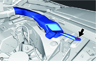
REMOVE NO. 6 REAR AIR DUCT
-
Using a clip remover, remove the clip.
-
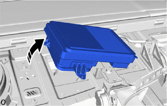
Lift the No. 6 rear air duct in the direction indicated by the arrow shown in the illustration.
-
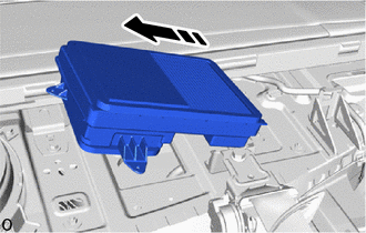
Remove the No. 6 rear air duct in the direction indicated by the arrow shown in the illustration.
-
-
REMOVE LUGGAGE COMPARTMENT FLOOR MAT
-
REMOVE TOOL BOX
-
REMOVE INNER LOWER LUGGAGE COMPARTMENT TRIM COVER
-
REMOVE LUGGAGE COMPARTMENT TRIM COVER LH
-
REMOVE LUGGAGE COMPARTMENT TRIM COVER RH
-
REMOVE ROPE HOOK ASSEMBLY
-
REMOVE REAR FLOOR FINISH PLATE
-
REMOVE FRONT LUGGAGE COMPARTMENT TRIM COVER
-
REMOVE NO. 1 LUGGAGE COMPARTMENT LIGHT ASSEMBLY
-
REMOVE REAR LUGGAGE COMPARTMENT TRIM COVER
-
REMOVE SIDE TRIM BOX
-
REMOVE LUGGAGE COMPARTMENT TRIM COVER ASSEMBLY RH
-
REMOVE LUGGAGE COMPARTMENT TRIM COVER ASSEMBLY LH
-
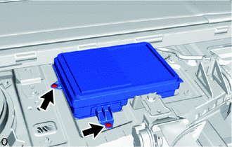
REMOVE AIR CONDITIONING TUBE AND ACCESSORY ASSEMBLY
-
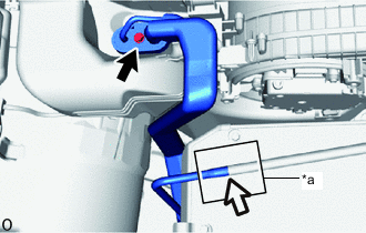
*a Packing 
Bolt 
Drain Hose Remove the packing and disconnect the drain hose connection.
-
Remove the bolt.
-
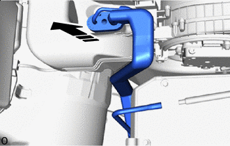

Remove in this Direction Slightly moving the air conditioning tube and accessory assembly in the direction indicated by the arrow shown in the illustration, disconnect it from the rear cooling unit.
-
Remove the 2 O-rings from the air conditioning tube and accessory assembly.
Note
Seal the openings of the disconnected parts using vinyl tape to prevent entry of moisture and foreign matter.
-
-
REMOVE REAR COOLING UNIT ASSEMBLY
-
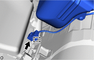
Disconnect the connector and detach the clamp.
-
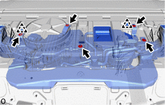
Remove the 5 nuts, detach the clip and remove the rear cooling unit assembly.
-