CAUTION / NOTICE / HINT
The necessary procedures (adjustment, calibration, initialization, or registration) that must be performed after parts are removed, installed, or replaced during the engine unit removal/installation are shown below.
| Replaced Part or Performed Procedure | Necessary Procedure | Effect/Inoperative Function when Necessary Procedure not Performed | Link |
|---|---|---|---|
| Auxiliary battery terminal is disconnected/reconnected | Memorize steering angle neutral point | Lane-keeping assist system (for Mono camera type) | for Stereo Camera type: for Mono Camera type: |
| Lane control system (for Stereo camera type) | |||
| Parking support brake system*1 | |||
| Pre-collision system (for Mono camera type) | |||
| Pre-collision system (for Stereo camera type) | |||
| AFS (Front-lighting adaptive system) | |||
|
|||
| Variable gear ratio steering system | |||
| Parking assist monitor system | |||
| Panoramic view monitor system | |||
| Initialize rear door sunshade system | Rear door sunshade system | ||
| Initialize power trunk lid system | Power trunk lid system | ||
| Replacement of ECM | Vehicle Identification Number (VIN) registration | DTC P063051 is output | w/ Canister Pump Module w/o Canister Pump Module |
|
Inspection after repairs |
|
w/ Canister Pump Module w/o Canister Pump Module |
| Replacement of engine assembly | Inspection after repair | ||
| Drive learning*2 |
|
L310: L310F: |
|
| Parts between the steering wheel and tires have been removed/installed, replaced or adjusted | Perform Actuator Angle Neutral Point Calibration and Initialization |
|
|
| Front bumper assembly (Including removal and installation) |
|
Parking support brake system | |
| Front television camera view adjustment | Panoramic view monitor system | ||
| Suspension, tires, etc |
|
Parking support brake system | |
|
Panoramic view monitor system | ||
| Rear television camera assembly optical axis (Back camera position setting) | Parking assist monitor system |
PROCEDURE
- Click here
REMOVE FRONT NO. 1 ENGINE MOUNTING BRACKET LH
-
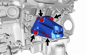
for 2WD:
-
Remove the 4 bolts and front No. 1 engine mounting bracket LH.
-
-
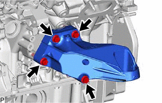
for AWD:
-
Remove the 4 bolts and front No. 1 engine mounting bracket LH.
-
-
- Click here
REMOVE FRONT NO. 1 ENGINE MOUNTING BRACKET RH
-
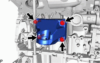
for 2WD:
-
Remove the 4 bolts and front No. 1 engine mounting bracket RH.
-
-
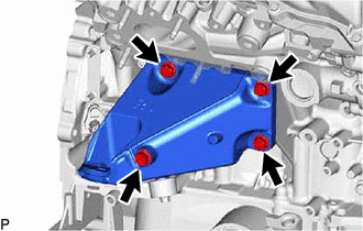
for AWD:
-
Remove the 4 bolts and front No. 1 engine mounting bracket RH.
-
-
- Click here
REMOVE V-RIBBED BELT
- Click here
REMOVE COMPRESSOR WITH MOTOR ASSEMBLY
- Click here
REMOVE NO. 1 COMPRESSOR MOUNTING BRACKET
-

for 2WD:
-
Remove the 4 bolts and No. 1 compressor mounting bracket.
-
-
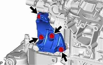
for AWD:
-
Remove the 4 bolts and No. 1 compressor mounting bracket.
-
-
- Click here
REMOVE NO. 6 WATER BY-PASS HOSE
-
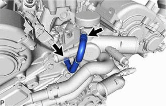
Slide the 2 hose clamps and remove the No. 6 water by-pass hose.
-
- Click here
REMOVE NO. 2 WATER BY-PASS HOSE
-
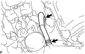
Slide the 2 hose clamps and remove the No. 2 water by-pass hose.
-
- Click here
REMOVE WATER HOSE SUB-ASSEMBLY
-
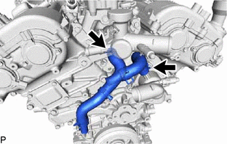
Slide the 2 hose clamps and remove the 2 water hose sub-assemblies.
-
- Click here
REMOVE WATER BY-PASS PIPE ASSEMBLY (w/ Oil Cooler)
-
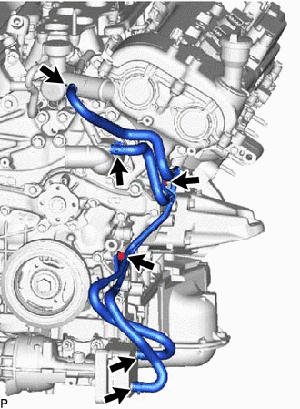
Slide the 4 hose clamps and disconnect the 4 water by-pass hoses.
-
Remove the bolt, nut and water by-pass pipe assembly.
-
- Click here
REMOVE WATER INLET CAP (w/o Oil Cooler)
-
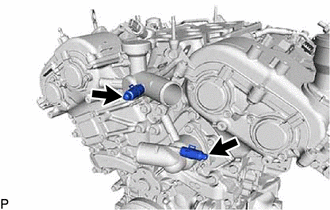
Slide the 2 hose clamps and remove the 2 water inlet caps.
-
- Click here
REMOVE NO. 4 WATER BY-PASS HOSE
-
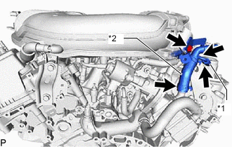
*1 No. 4 Water By-pass Hose *2 No. 3 Water By-pass Hose Assembly Slide the 2 hose clamps and remove the No. 4 water by-pass hose.
-
- Click here
REMOVE NO. 3 WATER BY-PASS HOSE ASSEMBLY
-
Remove the nut.
-
Slide the hose clamp and remove the No. 3 water by-pass hose assembly.
-
- Click here
REMOVE THROTTLE BODY BRACKET
- Click here
REMOVE EGR VALVE ASSEMBLY
- Click here
REMOVE EGR COOLER ASSEMBLY
- Click here
REMOVE NO. 2 WATER BY-PASS PIPE ASSEMBLY
-
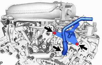
Remove the 2 bolts.
-
Slide the hose clamp and remove the No. 2 water by-pass pipe assembly.
-
- Click here
REMOVE INTAKE AIR SURGE TANK ASSEMBLY
- Click here
REMOVE ENGINE WIRE
-
*1 Oil Cooler Outlet Hose Bracket - - Bolt V-bank Cover BracketClick here
REMOVE WIRE HARNESS CLAMP BRACKET
-
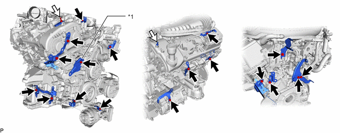
*1 Oil Cooler Outlet Hose Bracket - - 
Bolt 
V-bank Cover Bracket for 2WD:
-
Remove the 2 V-bank cover brackets and wire harness clamp bracket.
-
Remove the bolt and oil cooler outlet hose bracket.
-
Remove the 17 bolts and 14 wire harness clamp brackets.
-
Remove the wire harness clamp bracket from the wire harness protector of the cylinder head cover RH.
-
-
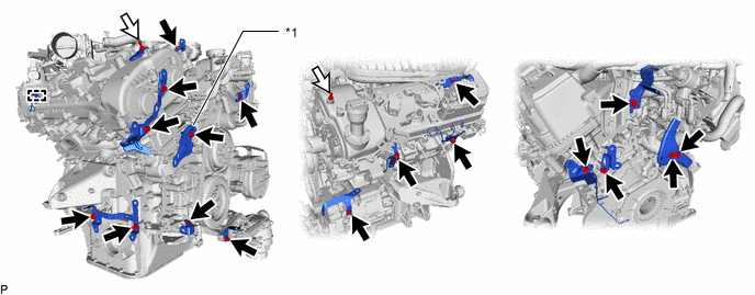
*1 Oil Cooler Outlet Hose Bracket - - Bolt V-bank Cover Bracket for AWD:
-
Remove the 2 V-bank cover brackets and wire harness clamp bracket.
-
Remove the bolt and oil cooler outlet hose bracket.
-
Remove the 17 bolts and 14 wire harness clamp brackets.
-
Remove the wire harness clamp bracket from the wire harness protector of the cylinder head cover RH.
-
-
- Click here
REMOVE FUEL DELIVERY PIPE SUB-ASSEMBLY
- Click here
REMOVE FUEL INJECTOR ASSEMBLY (for Port Injection)
- Click here
REMOVE INTAKE MANIFOLD
- Click here
REMOVE NO. 1 FUEL PIPE SUB-ASSEMBLY
- Click here
REMOVE FUEL PUMP ASSEMBLY
- Click here
REMOVE NO. 2 FUEL PIPE SUB-ASSEMBLY
- Click here
REMOVE FUEL DELIVERY PIPE WITH SENSOR ASSEMBLY LH
- Click here
REMOVE FUEL DELIVERY PIPE RH
- Click here
REMOVE FUEL INJECTOR ASSEMBLY (for Direct Injection)
- Click here
REMOVE FUEL INJECTOR SEAL
- Click here
REMOVE IGNITION COIL ASSEMBLY