FRAME WIRE REMOVAL

CAUTION / NOTICE / HINT
The necessary procedures (adjustment, calibration, initialization, or registration) that must be performed after parts are removed and installed, or replaced during HV floor under wire removal/installation are shown below.
| Replacement Part or Procedure | Necessary Procedure | Effect/Inoperative when not Performed | Link |
|---|---|---|---|
| Disconnect cable from negative auxiliary battery terminal | Memorize steering angle neutral point | LKA/LDA system (for Mono camera type) | for Stereo Camera type: Click here for Mono Camera type: Click here |
| Lane control system (for Stereo camera type) | |||
| Parking support brake system*1 | |||
| Pre-collision system (for Mono camera type) | |||
| Pre-collision system (for Stereo camera type) | |||
| Adaptive high beam system | |||
Lighting system (EXT) |
|||
| Variable gear ratio steering system | |||
| Parking assist monitor system | |||
| Panoramic view monitor system | |||
| Initialize rear door sunshade system | Rear door sunshade system | ||
| Initialize power trunk lid system | Power trunk lid system | ||
| ECM | Vehicle Identification Number (VIN) registration | DTC P063051 is output | w/ Canister Pump Module: Click here w/o Canister Pump Module: Click here |
|
Inspection after repair |
|
w/ Canister Pump Module: Click here w/o Canister Pump Module: Click here |
| Engine assembly | Inspection after repair | ||
| Drive learning*2 |
|
L310: Click here L310F: Click here |
|
| Parts between the steering wheel and tires have been removed/installed, replaced or adjusted | Perform actuator angle neutral point calibration and initialization |
|
|
| Suspension, tires, etc. |
|
Parking support brake system | |
|
Panoramic view monitor system | ||
| Rear television camera assembly optical axis (Back camera position setting) | Parking assist monitor system | ||
for LHD: |
Initialize position control ECU | Rear power seat control system |
Click here Click here
*2: After performing the confirmation driving pattern, if the shock during acceleration is large after calibrating the "A/T Code Reset", perform driving learning.
CAUTION:
-
Orange wire harnesses and connectors indicate high-voltage circuits. To prevent electric shock, always follow the procedure described in the repair manual.
-

To prevent electric shock, wear insulated gloves when working on wire harnesses and components of the high voltage system.
PROCEDURE
-
PRECAUTION
Note
After turning the power switch off, waiting time may be required before disconnecting the cable from the negative (-) auxiliary battery terminal. Therefore, make sure to read the disconnecting the cable from the negative (-) auxiliary battery terminal notices before proceeding with work.
-
REMOVE LUGGAGE COMPARTMENT MAT SUB-ASSEMBLY
-
DISCONNECT CABLE FROM NEGATIVE AUXILIARY BATTERY TERMINAL
Note
When disconnecting the cable, some systems need to be initialized after the cable is reconnected.
-
REMOVE SERVICE PLUG GRIP
-
REMOVE CONNECTOR COVER ASSEMBLY
-
CHECK TERMINAL VOLTAGE
-
TEMPORARILY INSTALL CONNECTOR COVER ASSEMBLY
-
REMOVE ENGINE ASSEMBLY WITH TRANSMISSION
-
REMOVE FUEL TANK ASSEMBLY
-
REMOVE REAR SUSPENSION MEMBER SUB-ASSEMBLY
-
REMOVE REAR SEAT CUSHION ASSEMBLY (for Fixed Seat Type)
-
REMOVE REAR SEAT CUSHION LOCK HOOK (for Fixed Seat Type)
-
REMOVE NO. 1 SEAT ARMREST CAP (for Fixed Seat Type)
-
REMOVE REAR SEATBACK ASSEMBLY (for Fixed Seat Type)
-
REMOVE REAR SEAT BACK HOLDER (for Fixed Seat Type)
-
REMOVE REAR SEAT CUSHION ASSEMBLY LH (for Power Seat)
-
REMOVE REAR SEAT CUSHION ASSEMBLY RH (for Power Seat)
-
REMOVE REAR SEAT CUSHION LOCK HOOK (for Power Seat)
-
REMOVE REAR CENTER SEAT ARMREST ASSEMBLY (for Power Seat)
-
REMOVE REAR CENTER SEAT CUSHION ASSEMBLY (for Power Seat)
-
REMOVE REAR SEATBACK ASSEMBLY LH (for Power Seat)
-
REMOVE REAR SEATBACK ASSEMBLY RH (for Power Seat)
-
REMOVE REAR DOOR SCUFF PLATE RH
-
REMOVE REAR SEAT SIDE GARNISH RH
-
REMOVE ROOM PARTITION BOARD ASSEMBLY LH (for Power Seat)
-
REMOVE ROOM PARTITION BOARD ASSEMBLY RH (for Power Seat)
-
REMOVE NO. 2 EV BATTERY INTAKE DUCT
-
REMOVE CENTER ROOM PARTITION GARNISH ASSEMBLY (for Power Seat)
-
REMOVE NO. 1 SEAT RECLINING ADJUSTER ASSEMBLY RH (for Power Seat)
-
REMOVE CENTER NO. 1 FLOOR TO BLACE EXTENSION
-
REMOVE NO. 10 HV BATTERY SHIELD PANEL
-
REMOVE FRONT NO. 6 FLOOR HEAT INSULATOR
-
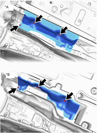
*A for 2WD *B for AWD Remove the 3 nuts and front No. 6 floor heat insulator.
-
-
REMOVE FRONT NO. 5 FLOOR HEAT INSULATOR
-
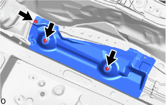
Remove the 3 nuts and front No. 5 floor heat insulator.
-
-
REMOVE FRONT NO. 2 FLOOR HEAT INSULATOR SUB-ASSEMBLY
-
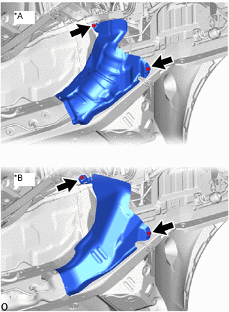
*A for 2WD *B for AWD Remove the 2 bolts and front No. 2 floor heat insulator sub-assembly.
-
-
REMOVE FRONT NO. 1 FLOOR HEAT INSULATOR SUB-ASSEMBLY
-
Remove the 2 bolts and front No. 1 floor heat insulator sub-assembly.
-
-
REMOVE HV FLOOR UNDER WIRE
CAUTION:
Wear insulated gloves.
-
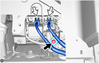
Remove the nut and disconnect the 2 connectors.
-
Detach the claw and Remove the battery terminal connector cover.
-
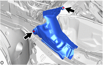
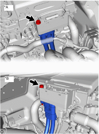
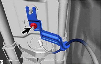
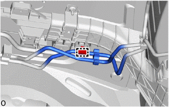
Remove the nut and disconnect the HV floor under wire.
-
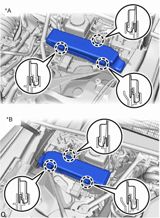
*A for LHD *B for RHD Detach the 3 claws and Remove the relay block cover.
-
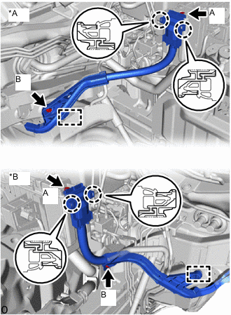
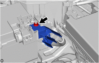
*A for LHD *B for RHD Remove the bolt A.
-
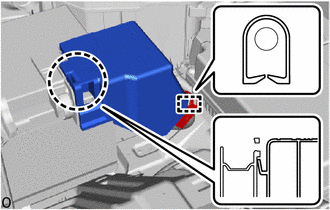
Detach the 2 claws and disconnect the HV floor under wire from the engine room relay block.
-
Remove the bolt B.
-
Detach the clamp.
-
*A for LHD *B for RHD for LHD:
Remove the 2 nuts and wiring harness clamp bracket.
-
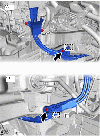
Remove the bolt.
-
Detach the clamp.
-
Remove the connector cover assembly.
-
*A for LHD *B for RHD Remove the bolt.
-
Disconnect the HV floor under wire.
Note
-
Do not allow any foreign matter or water to enter the inverter with converter assembly.
-
Do not touch the connector waterproofing rubber or terminals.
-
Do not damage the connectors, connector housings or inverter with converter assembly during disconnection.
-
Insulate the removed connectors with insulating tape.
-
Cover the hole where the cable was connected with tape (non-residue type) or equivalent to prevent entry of foreign matter.
-
-
Temporarily install the connector cover assembly.
-
Remove the nut and No. 1 parking lock release cable clamp bracket from the body.
-
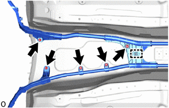
Remove the 5 nuts.
-
Detach the clamp.
-
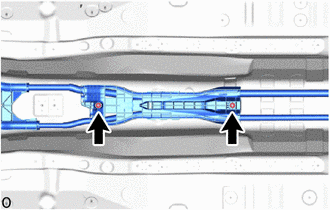
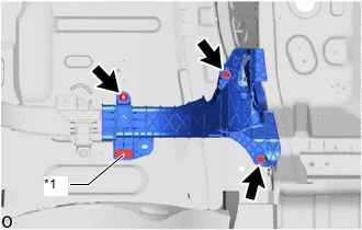
Remove the 2 nuts.
-
*1 Stud Clamp Remove the 2 bolts.
-
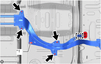
Remove the 2 nuts.
-
Detach the clamp.
-
Detach the grommet and pull out the hybrid under floor wire to the outside of the vehicle.
-
Remove the stud clamp.
Tech Tips
When removing the stud clamp, break the claw on the stud clamp. The stud clamp cannot be reused.
-
w/ Air Suspension:
-
Detach the clamp and No. 9 height control tube from the wiring harness protector.
-
-
*1 Stud Clamp Remove the 2 bolts and nut.
-
Remove the stud clamp and wiring harness protector.
Tech Tips
When removing the stud clamp, break the claw on the stud clamp. The stud clamp cannot be reused.
-
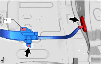
*1 Stud Clamp Detach the clamp.
-
Remove the nut and pull out the hybrid under floor wire to the outside of the vehicle.
-
Remove the stud clamp.
Tech Tips
When removing the stud clamp, break the claw on the stud clamp. The stud clamp cannot be reused.
-