REAR AXLE HUB INSTALLATION

CAUTION / NOTICE / HINT
Note
-
When using a vise, place aluminum plates between the part and vise.
-
When using a vise, do not overtighten it.
Tech Tips
-
Use the same procedure for the RH and LH side.
-
The following procedure is for the LH side.
PROCEDURE
-
INSTALL REAR AXLE HUB AND BEARING ASSEMBLY LH
-
Install the parking brake anchor block sub-assembly, cable support bracket and parking brake plate from the rear axle carrier with the 2 nuts.
- Torque:
- 75.5 N*m { 770 kgf*cm, 56 ft.*lbf }
-
Install the parking brake plate LH and the rear axle hub and bearing assembly LH to the rear axle carrier LH with the 4 bolts.
- Torque:
- 97 N*m { 989 kgf*cm, 72 ft.*lbf }
-
-
INSTALL REAR NO. 1 WHEEL BEARING DUST DEFLECTOR LH
-
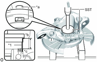
*1 No. 1 Rear Wheel Bearing Dust Deflector LH *a Align *b No. 1 Rear Wheel Bearing Dust Deflector LH End Face *c Rear Axle Hub Bearing Outer Race End Face Using SST and a press, press a new No. 1 rear wheel bearing dust deflector LH into the rear axle carrier while checking the sensor installation hole position.
- SST
- 09950-70010 ( 09951-07150 )
- 09951-01000
Standard Length 23.3 to 23.9 mm (0.918 to 0.940 in.) Note
Align the installation hole of the No. 1 rear wheel bearing dust deflector LH with the installation hole of the speed sensor on the rear axle carrier.
-
-
INSTALL REAR AXLE ASSEMBLY
-
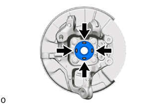
Apply TOYOTA body grease W to the entire contact surface between the rear drive shaft assembly and rear axle hub sub-assembly surface or only apply 0.1 to 0.3 g (0.00353 to 0.0105 oz.) of TOYOTA body grease W to the 4 areas on the axle hub bearing shown in the illustration.
-
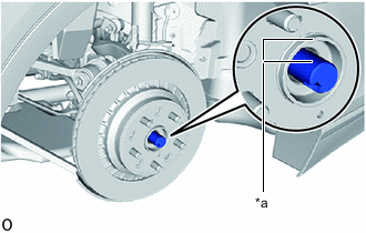
*a Matchmark Align the rear axle assembly with the matchmark and install it to the rear drive shaft assembly.
-
-
TEMPORARILY INSTALL REAR SHOCK ABSORBER ASSEMBLY LH (w/o Air Suspension)
-
Temporarily install the washer and rear shock absorber assembly LH (lower side) with a new nut.
-
-
TEMPORARILY INSTALL REAR PNEUMATIC CYLINDER WITH SHOCK ABSORBER ASSEMBLY LH (w/ Air Suspension)
Tech Tips
Use the same procedure for the rear shock absorber assembly LH.
-
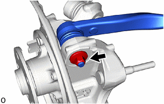
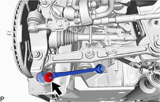
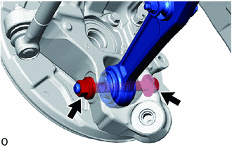
CONNECT REAR NO. 1 SUSPENSION ARM ASSEMBLY LH
-
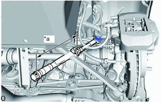
*a Torque Wrench Fulcrum Length Using ball joint lock nut wrench, fully tighten nut.
- Torque:
- Specified tightening torque
- 160 N*m { 1632 kgf*cm, 118 ft.*lbf }
Tech Tips
-
Calculate the torque wrench reading when changing the fulcrum length of the torque wrench.
-
When using a ball joint lock nut wrench (fulcrum length of 150 mm (5.906 in.)) + torque wrench (fulcrum length of 600 mm (23.622 in.)): 128 N*m (1305 kgf*cm, 94 ft.*lbf)
-
-
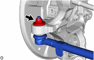
CONNECT REAR UPPER CONTROL ARM ASSEMBLY LH
-
Fully tighten a new nut.
- Torque:
- 160 N*m { 1632 kgf*cm, 118 ft.*lbf }
-
-
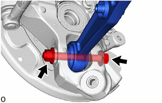
CONNECT TOE CONTROL LINK SUB-ASSEMBLY LH (w/o Dynamic Rear Steering)
-
Connect the toe control link sub-assembly LH with a new nut.
- Torque:
- 118 N*m { 1203 kgf*cm, 87 ft.*lbf }
-
-
CONNECT REAR STEERING TIE ROD ASSEMBLY LH (w/ Dynamic Rear Steering)
-
TEMPORARILY TIGHTEN REAR NO. 2 SUSPENSION ARM ASSEMBLY LH
-
Insert the bolt from the front of the vehicle. Then temporarily tighten the rear No. 2 suspension arm assembly LH with the nut and washer.
-
-
TEMPORARILY TIGHTEN LOWER CONTROL ARM ASSEMBLY LH
-
Temporarily tighten the lower control arm assembly LH with a new nut.
-
-
TEMPORARILY TIGHTEN REAR STABILIZER LINK ASSEMBLY LH
-
INSTALL PARKING BRAKE
-
TEMPORARILY TIGHTEN REAR AXLE SHAFT NUT LH
-
Using a 32 mm socket wrench, while applying the brakes, temporarily install the rear axle shaft nut.
- Torque:
- 290 N*m { 2957 kgf*cm, 214 ft.*lbf }
Note
Stake the rear axle shaft nut after inspecting for looseness and runout in the following steps.
Tech Tips
Keep depressing the brake pedal to prevent the rear drive shaft assembly from rotating.
-
-
INSPECT REAR AXLE HUB BEARING LOOSENESS
-
INSPECT REAR AXLE HUB RUNOUT
-
INSTALL REAR DISC LH
-
for 4-Pot Caliper:
-
except 4-Pot Caliper:
-
-
ADJUST BRAKE DISC INSIDE DIAMETER
-
INSTALL PARKING BRAKE SHOE ADJUSTING HOLE PLUG
-
for 4-Pot Caliper:
-
except 4-Pot Caliper:
-
-
INSTALL REAR SPEED SENSOR LH
-
CONNECT SKID CONTROL SENSOR WIRE
-
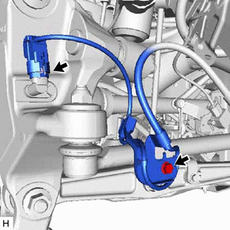
for LH Side:
-
Install the sensor clamp with the bolt.
- Torque:
- 8.5 N*m { 87 kgf*cm, 75 in.*lbf }
-
Connect the speed sensor connector to the rear speed sensor LH.
-
-
for RH Side:
-
Install the sensor clamp with the bolt.
- Torque:
- 8.5 N*m { 87 kgf*cm, 75 in.*lbf }
-
Connect the speed sensor connector to the rear speed sensor RH.
-
Connect the pad wear indicator connector.
-
-
-
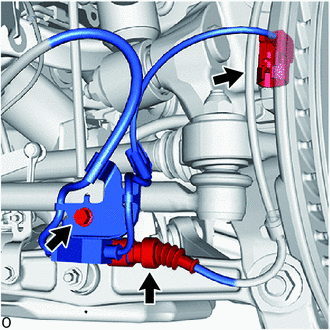
CONNECT REAR DISC BRAKE CYLINDER ASSEMBLY
-
Install the rear disc brake cylinder assembly LH to the steering knuckle with the 2 bolts.
- Torque:
- 151 N*m { 1540 kgf*cm, 111 ft.*lbf }
Note
-
Do not twist the flexible hose.
-
Make sure that the threaded portion is free from damage and foreign matter.
-
Do not overtighten the bolts, as the threaded portion is part of the aluminum hub carrier.
-
for RH side:
-
Attach the 4 clamps to connect the pad wear indicator assembly to the parking brake plate.
-
-
-
INSTALL REAR AXLE SHAFT NUT LH
-
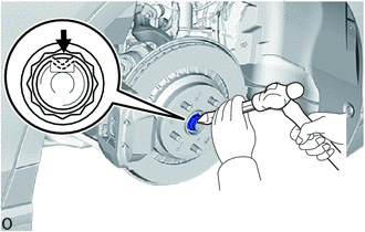
Using a chisel and hammer, stake the rear axle shaft nut LH.
-
-
STABILIZE SUSPENSION
-
FULLY TIGHTEN REAR SHOCK ABSORBER ASSEMBLY LH
-

Fully tighten the nut.
- Torque:
- 110 N*m { 1122 kgf*cm, 81 ft.*lbf }
-
-
FULLY TIGHTEN REAR PNEUMATIC CYLINDER ASSEMBLY LH WITH SHOCK ABSORBER (w/ Air Suspension)
Tech Tips
Use the same procedure for the rear shock absorber assembly LH.
-
FULLY TIGHTEN REAR STABILIZER LINK ASSEMBLY LH
-
CONNECT REAR HEIGHT CONTROL SENSOR SUB-ASSEMBLY LH
-
FULLY TIGHTEN LOWER CONTROL ARM ASSEMBLY LH
-
Fully tighten the nut.
- Torque:
- 118 N*m { 1203 kgf*cm, 87 ft.*lbf }
-
-
FULLY TIGHTEN REAR NO. 2 SUSPENSION ARM ASSEMBLY LH
-
Fully tighten the nut.
- Torque:
- 165 N*m { 1683 kgf*cm, 122 ft.*lbf }
-
-
FULLY TIGHTEN TOE CONTROL LINK SUB-ASSEMBLY LH
-
Fully tighten the nut (rear axle carrier sub-assembly LH side).
- Torque:
- 118 N*m { 1203 kgf*cm, 87 ft.*lbf }
-
-
ADJUST PARKING BRAKE
-
INSTALL REAR WHEEL
-
CONNECT BRAKE BOOSTER PUMP CONNECTOR
-
INSPECT AND ADJUST REAR WHEEL ALIGNMENT
-
CHECK FOR SPEED SENSOR SIGNAL
-
PERFORM DYNAMIC REAR STEERING SYSTEM CALIBRATION (w/ Dynamic Rear Steering)
-
INSPECT AND ADJUST VEHICLE HEIGHT (w/ Air Suspension)
-
PERFORM INITIALIZATION
Parking support brake system Panoramic view monitor system Parking assist monitor system
-
Lighting system (EXT)
w/o Air Suspension System:
-
-
ADJUST HEADLIGHT AIMING