CAUTION / NOTICE / HINT
The necessary procedures (adjustment, calibration, initialization or registration) that must be performed after parts are removed and installed, or replaced during shift control ECU removal/installation are shown below.
After turning the power switch off, waiting time may be required before disconnecting the cable from the negative (-) auxiliary battery terminal. Therefore, make sure to read the disconnecting the cable from the negative (-) auxiliary battery terminal notices before proceeding with work.
| Replaced Part or Performed Procedure | Necessary Procedure | Effect/Inoperative Function when Necessary Procedure not Performed | Link |
|---|---|---|---|
| Auxiliary battery terminal is disconnected/reconnected | Memorize steering angle neutral point | LKA/LDA system (for Mono camera type) | for Stereo Camera type:Click here for Mono Camera type:Click here |
| Lane control system (for Stereo camera type) | |||
| Parking support brake system*1 | |||
| Pre-collision system (for Stereo camera type) | |||
| Pre-collision system (for Mono camera type) | |||
| Adaptive high beam system | |||
|
|||
| Variable gear ratio steering system | |||
| Parking assist monitor system | |||
| Panoramic view monitor system | |||
| Initialize rear door sunshade system | Rear door sunshade system | ||
| Initialize power trunk lid system | Power trunk lid system |
After the power switch is turned off, the navigation system requires approximately a minute to record various types of memory and settings. As a result, after turning the power switch off, wait a minute or more before disconnecting the cable from the negative (-) auxiliary battery terminal.
PROCEDURE
- Click here
REMOVE LUGGAGE COMPARTMENT MAT SUB-ASSEMBLY
- Click here
REMOVE TOOL BOX
- Click here
PRECAUTION
CAUTION:Note:After turning the power switch off, waiting time may be required before disconnecting the cable from the negative (-) auxiliary battery terminal. Therefore, make sure to read the disconnecting the cable from the negative (-) auxiliary battery terminal notices before proceeding with work.
- Click here
DISCONNECT CABLE FROM NEGATIVE AUXILIARY BATTERY TERMINAL
Note:It is necessary to remove the shift control ECU while no power is being supplied from the sub-battery. Therefore, perform the following procedures.
-
Turn the power switch off.
-
Check that the ODO meter display has turned off.
Tip:The ODO meter continues to display for 30 seconds after turning off. Therefore, allow sufficient time for the shift control ECU to enter sleep mode and for the sub-battery power supply to end. In addition to monitoring the sub-battery voltage directly, the only other method for checking on the vehicle is to use the ODO meter display.
-
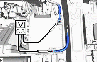
Check that the voltage between the terminals of the sub-battery assembly with control is 0 V.
-
Disconnect the cable from the negative (-) auxiliary battery terminal.
Note:When disconnecting the cable, some systems need to be initialized after the cable is reconnected.
-
- Click here
REMOVE GLOVE COMPARTMENT DOOR ASSEMBLY
- Click here
REMOVE NO. 2 AIR DUCT SUB-ASSEMBLY (for LHD)
- Click here
REMOVE NO. 2 AIR DUCT SUB-ASSEMBLY (for RHD)
- Click here
REMOVE SHIFT CONTROL ECU
-
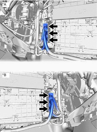
*A for LHD *B for RHD Disconnect the 3 shift control ECU connectors.
-
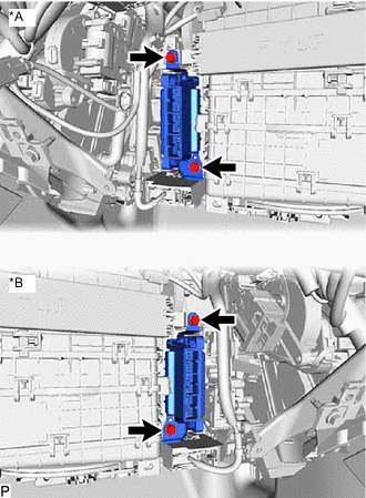
*A for LHD *B for RHD Remove the 2 bolts and shift control ECU.
-
- Click here
REMOVE NO. 1 SHIFT CONTROL ECU BRACKET
-
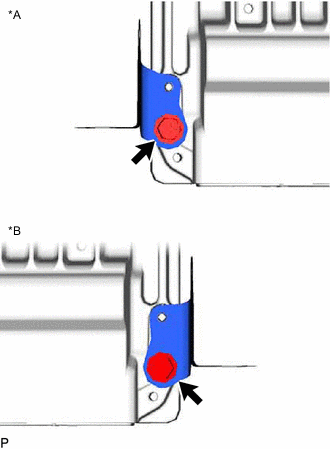
*A for LHD *B for RHD Remove the bolt and No. 1 shift control ECU bracket from the shift control ECU.
-
- Click here
REMOVE NO. 2 SHIFT CONTROL ECU BRACKET
-
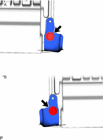
*A for LHD *B for RHD Remove the bolt and No. 2 shift control ECU bracket from the shift control ECU.
-