ENGINE ASSEMBLY INSTALLATION
CAUTION / NOTICE / HINT
CAUTION:
-
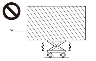
*a Heavy object exceeding the capacity of the engine lifter Because the weight of the engine with transmission assembly is extremely heavy, make sure to follow the work procedures described in the repair manual.
-
If work is not performed according to the procedures described in the repair manual, there is a danger that the engine lifter could drop and components could fall down.
Tech Tips
Perform "Inspection After Repairs" after replacing the engine assembly, cylinder head sub-assembly, camshaft timing control motor with EDU assembly, camshaft (for intake or exhaust camshaft), camshaft timing intake gear assembly, camshaft timing exhaust gear assembly, piston sub-assembly or piston ring.
-
w/ Canister Pump Module:
-
w/o Canister Pump Module:
PROCEDURE
-
INSTALL NO. 1 ENGINE HANGER
-
REMOVE ENGINE FROM ENGINE STAND
-
Remove the engine assembly from the engine stand.
-
-
INSTALL FRONT ENGINE MOUNTING INSULATOR
Tech Tips
Perform this procedure only when replacement of the front engine mounting insulator is necessary.
-
Install the 2 front engine mounting insulators to the front suspension crossmember sub-assembly with the 2 nuts.
- Torque:
- 65 N*m { 663 kgf*cm, 48 ft.*lbf }
-
-
INSTALL FRONT FRAME CROSSMEMBER SUB-ASSEMBLY
-
Install the front suspension crossmember sub-assembly to the engine assembly with the 2 nuts.
- Torque:
- 57 N*m { 581 kgf*cm, 42 ft.*lbf }
-
-
INSTALL DRIVE PLATE AND RING GEAR SUB-ASSEMBLY
-
INSPECT DRIVE PLATE AND RING GEAR SUB-ASSEMBLY
-
INSTALL REAR ENGINE MOUNTING INSULATOR
-
INSTALL REAR ENGINE MOUNTING MEMBER
Tech Tips
Perform this procedure only when replacement of the rear engine mounting member is necessary.
-
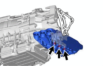
Install the engine rear mounting member to the rear engine mounting insulator with the 3 nuts.
- Torque:
- 34 N*m { 347 kgf*cm, 25 ft.*lbf }
-
-
INSTALL AUTOMATIC TRANSMISSION ASSEMBLY
-
INSTALL DRIVE PLATE AND TORQUE CONVERTER ASSEMBLY SETTING BOLT
-
INSTALL STARTER ASSEMBLY
-
INSTALL GENERATOR ASSEMBLY
-
INSTALL COMPRESSOR ASSEMBLY WITH PULLEY
-
INSTALL OIL COOLER TUBE
-
CONNECT WIRE HARNESS
-
INSTALL FAN AND GENERATOR V BELT
-
INSTALL NO. 3 EXHAUST MANIFOLD HEAT INSULATOR
-
INSTALL EXHAUST MANIFOLD TO HEAD GASKET LH
-
INSTALL EXHAUST MANIFOLD SUB-ASSEMBLY LH
-
INSTALL NO. 2 EXHAUST MANIFOLD HEAT INSULATOR
-
INSTALL EXHAUST MANIFOLD TO HEAD GASKET
-
INSTALL EXHAUST MANIFOLD SUB-ASSEMBLY RH
-
INSTALL NO. 1 EXHAUST MANIFOLD HEAT INSULATOR
-
INSTALL ENGINE MOUNTING DAMPER
-
Install the 2 engine mounting dampers with the 2 bolts.
- Torque:
- 10 N*m { 102 kgf*cm, 7 ft.*lbf }
-
-
INSTALL ENGINE OIL LEVEL DIPSTICK GUIDE
-
INSTALL ENGINE WITH TRANSMISSION ASSEMBLY
Tech Tips
Perform "Inspection After Repairs" after replacing the engine assembly.
-
w/ Canister Pump Module:
-
w/o Canister Pump Module:
-

Place Wooden Block or Plate Attachments Set the engine on an engine lifter.
Note
-
Place wooden blocks or plate lift attachments so that the engine is level.
-
With the exception of installing the engine assembly to an engine stand or removing the engine assembly from an engine stand, do not perform any work on the engine while it is suspended, as doing so is dangerous.
-
Never install attachments to the oil pan of the engine assembly or transmission as doing so may deform the oil pan.
-
-
Operate the engine lifter and install the engine and transmission assembly to the vehicle.
Note
Make sure that the engine is clear of all wiring and hoses.
-
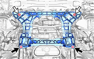

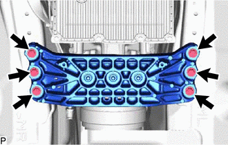
Bolt 
Nut Install the engine and transmission assembly to the vehicle with the 2 bolts and 2 nuts.
- Torque:
- 170 N*m { 1734 kgf*cm, 125 ft.*lbf }
-
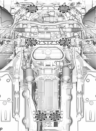
Install the rear engine mounting member with the 6 bolts.
- Torque:
- 34.7 N*m { 354 kgf*cm, 26 ft.*lbf }
-
Remove the 4 bolts and 2 engine hangers.
-
-
CONNECT NO. 2 GROUND WIRE
-
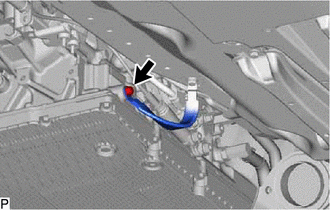
Connect the No. 2 ground wire with the bolt.
- Torque:
- 10 N*m { 102 kgf*cm, 7 ft.*lbf }
-
-
CONNECT NO. 2 PARKING LOCK RELEASE CABLE ASSEMBLY
-
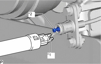
*1 Parking Lock Release Lever Assembly Cable End *2 No. 2 Parking Lock Release Cable Assembly Cable End Connect the parking lock release lever assembly cable end to the No. 2 parking lock release cable assembly cable end.
-
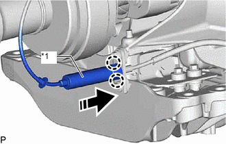
*1 Cover Arrow 
Connect Attach the 2 claws and connect the cover to the No. 2 parking lock release cable assembly as shown in the illustration.
-
-
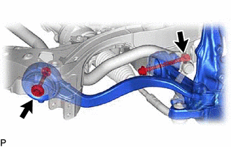
INSTALL REAR LOWER ARM MOUNTING REINFORCEMENT SUB-ASSEMBLY LH
-
INSTALL REAR LOWER ARM MOUNTING REINFORCEMENT SUB-ASSEMBLY RH
Tech Tips
Install the RH side following the same procedure as for the LH side.
-
INSTALL ENGINE SIDE COVER LH
-
INSTALL ENGINE SIDE COVER RH
Tech Tips
Install the RH side following the same procedure as for the LH side.
-
TEMPORARILY TIGHTEN STEERING KNUCKLE LH
-
Install the steering knuckle LH with the 2 bolts and 2 nuts.
-
-
TEMPORARILY TIGHTEN STEERING KNUCKLE RH
Tech Tips
Install the RH side following the same procedure as for the LH side.
-
CONNECT FRONT STABILIZER LINK ASSEMBLY LH
-
CONNECT FRONT STABILIZER LINK ASSEMBLY RH
Tech Tips
Install the RH side following the same procedure as for the LH side.
-
CONNECT TIE ROD ASSEMBLY LH
-
CONNECT TIE ROD ASSEMBLY RH
Tech Tips
Install the RH side following the same procedure as for the LH side.
-
INSTALL FRONT DISC BRAKE DUST COVER LH
-
INSTALL FRONT DISC BRAKE DUST COVER RH
Tech Tips
Install the RH side following the same procedure as for the LH side.
-
INSTALL FRONT DISC LH
-
INSTALL FRONT DISC RH
Tech Tips
Install the RH side following the same procedure as for the LH side.
-
CONNECT DISC BRAKE CYLINDER ASSEMBLY LH
-
CONNECT DISC BRAKE CYLINDER ASSEMBLY RH
Tech Tips
Install the RH side following the same procedure as for the LH side.
-
CONNECT FRONT HEIGHT CONTROL SENSOR SUB-ASSEMBLY LH
-
CONNECT FRONT HEIGHT CONTROL SENSOR SUB-ASSEMBLY RH
Tech Tips
Install the RH side following the same procedure as for the LH side.
-
CONNECT FRONT SKID CONTROL SENSOR WIRE LH
-
CONNECT FRONT SKID CONTROL SENSOR WIRE RH
Tech Tips
Install the RH side following the same procedure as for the LH side.
-
CONNECT STEERING SLIDING WITH SHAFT YOKE SUB-ASSEMBLY
-
INSTALL PROPELLER WITH CENTER BEARING SHAFT ASSEMBLY
-
INSTALL NO. 2 FUEL TANK PROTECTOR
-
INSTALL FRONT NO. 1 FLOOR HEAT INSULATOR
-
INSTALL NO. 1 EXHAUST PIPE SUPPORT BRACKET SUB-ASSEMBLY
-
INSTALL FRONT EXHAUST PIPE ASSEMBLY
-
INSTALL FRONT CENTER FLOOR BRACE SUB-ASSEMBLY
-
INSTALL HEATED OXYGEN SENSOR (for Bank 2)
-
INSTALL HEATED OXYGEN SENSOR (for Bank 1)
-
CONNECT HEATED OXYGEN SENSOR CONNECTOR
-
INSTALL FRONT SEAT ASSEMBLY
-
INSTALL FRONT FLOOR COVER LH
-
INSTALL FRONT FLOOR COVER RH
-
INSTALL FRONT FENDER SEAL LH
-
INSTALL FRONT FENDER SEAL RH
-
INSTALL REAR FLOOR SIDE MEMBER COVER LH
-
INSTALL REAR FLOOR SIDE MEMBER COVER RH
-
INSTALL REAR FRAME RAIL SUB-ASSEMBLY LH
-
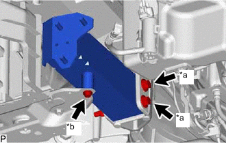
*a Bolt A *b Bolt B Install the rear frame rail sub-assembly LH with the 3 bolts and 2 nuts.
- Torque:
- Bolt A
- 28 N*m { 286 kgf*cm, 21 ft.*lbf }
- Bolt B
- 14 N*m { 143 kgf*cm, 10 ft.*lbf }
-
-
INSTALL REAR FRAME RAIL SUB-ASSEMBLY RH
-
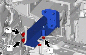
*a Bolt A *b Bolt B Install the rear frame rail sub-assembly RH with the 3 bolts and 2 nuts.
- Torque:
- Bolt A
- 28 N*m { 286 kgf*cm, 21 ft.*lbf }
- Bolt B
- 14 N*m { 143 kgf*cm, 10 ft.*lbf }
-
-
INSTALL RADIATOR SUPPORT OPENING COVER
-
INSTALL RADIATOR SUPPORT EXTENSION LH
-
INSTALL RADIATOR SUPPORT EXTENSION RH
-
INSTALL NO. 2 FRONT BUMPER REINFORCEMENT SUB-ASSEMBLY
-
Install the No. 2 front bumper reinforcement sub-assembly with the 6 nuts.
- Torque:
- 25 N*m { 255 kgf*cm, 18 ft.*lbf }
-
-
INSTALL FRONT BUMPER COVER
-
CONNECT NO. 3 ENGINE WIRE
-
Connect the No. 3 engine wire from the generator assembly with the bolt.
- Torque:
- 21 N*m { 214 kgf*cm, 15 ft.*lbf }
-
Attach the 2 clamps.
-
-
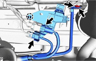
CONNECT NO. 3 ENGINE ROOM WIRE (for LHD)
-
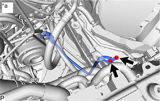
*a LH Side Connect the No. 3 engine room wire with the 2 bolts.
- Torque:
- 10 N*m { 102 kgf*cm, 7 ft.*lbf }
-
*a RH Side Attach the 3 clamps and connect the No. 3 engine room wire.
-
Connect the 2 connectors.
-
-
CONNECT NO. 3 ENGINE ROOM WIRE (for RHD)
-
Connect the No. 3 engine room wire with the 2 bolts.
- Torque:
- 10 N*m { 102 kgf*cm, 7 ft.*lbf }
-
Attach the claw and connect the No. 10 connector holder.
-
Connect the 2 connectors.
-
-
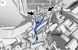
CONNECT ENGINE WIRE (for LHD)
-
Connect in this Direction Attach the 2 claws and connect the connector holder to the No. 1 engine room relay block.
-
Attach the claw and disconnect the junction connector.
-
Connect the 2 connectors.
-
Attach the 2 claws and connect the No. 1 semiconductor power integration ECU to the No. 1 engine room relay block.
-
Attach the clamp.
-
Connect the ECM connector.
-
Attach the 2 claws and connect the engine wire to the No. 1 engine room relay block.
-
Install the nut.
- Torque:
- 10 N*m { 102 kgf*cm, 7 ft.*lbf }
-
Attach the clamp.
-
-
CONNECT ENGINE WIRE (for RHD)
-
Connect in this Direction Attach the 2 claws and connect the connector holder to the No. 1 engine room relay block.
-
Attach the claw and disconnect the junction connector.
-
Connect the 2 connectors.
-
Attach the 2 claws and connect the No. 1 semiconductor power integration ECU to the No. 1 engine room relay block.
-
Attach the clamp.
-
Connect the ECM connector.
-
Attach the 2 claws and connect the engine wire to the No. 1 engine room relay block.
-
Install the nut.
- Torque:
- 10 N*m { 102 kgf*cm, 7 ft.*lbf }
-
Attach the clamp.
-
-
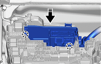
CONNECT NO. 2 ENGINE WIRE (for LHD)
-
Attach the 2 claws and connect the No. 2 engine wire to the No. 1 engine room relay block.
-
Tighten the nut.
- Torque:
- 10 N*m { 102 kgf*cm, 7 ft.*lbf }
-
Attach the 2 clamps.
-
Install the upper relay block cover to the No. 1 engine room relay block.
-
-
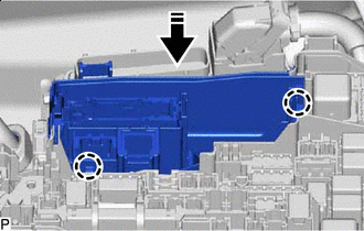
CONNECT NO. 2 ENGINE WIRE (for RHD)
-
Attach the 2 claws and connect the No. 2 engine wire to the No. 1 engine room relay block.
-
Tighten the nut.
- Torque:
- 10 N*m { 102 kgf*cm, 7 ft.*lbf }
-
Attach the 2 clamps.
-
Install the upper relay block cover to the No. 1 engine room relay block.
-
-
CONNECT SUCTION HOSE SUB-ASSEMBLY A
-
CONNECT DISCHARGE HOSE SUB-ASSEMBLY
-
CONNECT FUEL TUBE SUB-ASSEMBLY
-
Connect the fuel tube sub-assembly.
-
Install the fuel pipe clamp to the fuel tube sub-assembly.
-
-
CONNECT NO. 2 FUEL TUBE SUB-ASSEMBLY
-
Connect the No. 2 fuel tube sub-assembly.
-
Install the fuel pipe clamp to the No. 2 fuel tube sub-assembly.
-
-
CONNECT NO. 1 FUEL VAPOR FEED HOSE
-
Connect the No. 1 fuel vapor feed hose to the purge VSV and slide the clip to secure it.
-
-
CONNECT HEATER WATER OUTLET HOSE
-
Connect the heater water outlet hose to the No. 3 water by-pass pipe and slide the clip to secure it.
-
-
CONNECT HEATER WATER INLET HOSE
-
Connect the heater water inlet hose to the No. 3 water by-pass pipe and slide the clip to secure it.
-
-
CONNECT RADIATOR HOSE SUB-ASSEMBLY
-
INSTALL NO. 1 OIL COOLER OUTLET HOSE
-
INSTALL NO. 1 OIL COOLER INLET HOSE
-
CONNECT NO. 3 RADIATOR HOSE
-
INSTALL WATER BY-PASS HOSE
-
INSTALL NO. 4 TRANSMISSION OIL COOLER HOSE
-
CONNECT NO. 1 RADIATOR HOSE
-
INSTALL RESERVE TANK OUTLET HOSE
-
INSTALL RADIATOR RESERVE TANK ASSEMBLY
-
INSTALL NO. 2 INTAKE AIR CONNECTOR PIPE
-
INSTALL INTAKE AIR SOUND CREATOR
-
INSTALL INTAKE AIR CONNECTOR PIPE
-
INSTALL AIR CLEANER HOSE ASSEMBLY
-
Connect the air cleaner hose assembly to the throttle body with motor assembly.
-
Tighten the 2 hose clamps.
- Torque:
- 4.0 N*m { 41 kgf*cm, 35 in.*lbf }
-
-
CONNECT NO. 3 PCV HOSE
-
CONNECT NO. 2 PCV HOSE
-
INSTALL AIR CLEANER WITH ELEMENT ASSEMBLY RH
-
Connect the air cleaner with element assembly RH.
-
Insert the 3 air cleaner with element assembly RH pins into the air cleaner support bracket and radiator upper support.
-
Tighten the hose clamp.
- Torque:
- 4.0 N*m { 41 kgf*cm, 35 in.*lbf }
-
Connect the 2 vacuum hose sub-assemblies.
-
Attach the 2 clamps and connect the wire harness clamp to the air cleaner with element assembly RH.
-
Connect the vacuum switching valve assembly connector.
-
Connect the mass air flow meter sub-assembly connector.
-
-
INSTALL AIR CLEANER WITH ELEMENT ASSEMBLY LH
-
Connect the air cleaner with element assembly LH.
-
Insert the 3 air cleaner with element assembly LH pins into the air cleaner support bracket and radiator upper support.
-
Tighten the hose clamp.
- Torque:
- 4.0 N*m { 41 kgf*cm, 35 in.*lbf }
-
Connect the vacuum hose sub-assembly.
-
Attach the clamp and connect the wire harness clamp to the air cleaner with element assembly LH.
-
Connect the mass air flow meter sub-assembly connector.
-
-
INSTALL FENDER APRON BRACE SUB-ASSEMBLY LH (for LHD)
-
Install the fender apron brace sub-assembly LH with the 2 bolts.
- Torque:
- 49 N*m { 500 kgf*cm, 36 ft.*lbf }
-
-
INSTALL FENDER APRON BRACE SUB-ASSEMBLY LH (for RHD)
-
Install the fender apron brace sub-assembly LH with the 2 bolts.
- Torque:
- 49 N*m { 500 kgf*cm, 36 ft.*lbf }
-
Attach the 2 claws and install the center cowl top ventilator louver.
-
-
INSTALL FENDER APRON BRACE SUB-ASSEMBLY RH (for LHD)
-
Install the fender apron brace sub-assembly RH with the 2 bolts.
- Torque:
- 49 N*m { 500 kgf*cm, 36 ft.*lbf }
-
Attach the 2 claws and install the center cowl top ventilator louver.
-
-
INSTALL FENDER APRON BRACE SUB-ASSEMBLY RH (for RHD)
-
Install the fender apron brace sub-assembly RH with the 2 bolts.
- Torque:
- 49 N*m { 500 kgf*cm, 36 ft.*lbf }
-
-
INSTALL RADIATOR SUPPORT TO CROSSMEMBER BRACE SUB-ASSEMBLY LH
-
INSTALL RADIATOR SUPPORT TO CROSSMEMBER BRACE SUB-ASSEMBLY RH
-
CONNECT CABLE TO NEGATIVE BATTERY TERMINAL
Note
When disconnecting the cable, some systems need to be initialized after the cable is reconnected.
-
PERFORM INITIALIZATION
-
PARKING LOCK FORCED RELEASE
-
CHECK SHIFT LEVER OPERATION
-
ADD ENGINE OIL
-
ADD ENGINE COOLANT
-
ADD AUTOMATIC TRANSMISSION FLUID
-
CHARGE AIR CONDITIONING SYSTEM WITH REFRIGERANT
-
for HFC-134a(R134a):
-
for HFO-1234yf(R1234yf):
-
-
WARM UP ENGINE
-
for HFC-134a(R134a):
-
for HFO-1234yf(R1234yf):
-
-
INSPECT FOR COOLANT LEAK
-
INSPECT FOR ENGINE OIL LEAK
-
INSPECT FOR FUEL LEAK
-
INSPECT FOR EXHAUST GAS LEAK
-
INSPECT FOR REFRIGERANT LEAK
-
for HFC-134a(R134a):
-
for HFO-1234yf(R1234yf):
-
-
INSTALL FRONT WHEELS
-
STABILIZE SUSPENSION
-
FULLY TIGHTEN LOWER NO. 2 SUSPENSION ARM ASSEMBLY LH
-
FULLY TIGHTEN LOWER NO. 2 SUSPENSION ARM ASSEMBLY RH
Tech Tips
Install the RH side following the same procedure as for the LH side.
-
FULLY TIGHTEN FRONT LOWER SUSPENSION ARM ASSEMBLY LH
-
FULLY TIGHTEN FRONT LOWER SUSPENSION ARM ASSEMBLY RH
Tech Tips
Install the RH side following the same procedure as for the LH side.
-
ALIGN FRONT WHEELS FACING STRAIGHT AHEAD
-
INSPECT AND ADJUST FRONT WHEEL ALIGNMENT
-
VARIABLE GEAR RATIO STEERING SYSTEM CALIBRATION
-
INSPECT THROTTLE WITH MOTOR BODY ASSEMBLY
-
INSPECT IGNITION TIMING
-
INSPECT ENGINE IDLE SPEED
-
INSPECT CO/HC
-
INSPECT ENGINE COOLANT LEVEL IN RESERVOIR
-
CHECK ENGINE OIL LEVEL
-
INSTALL STRUT BAR BRACKET SUPPORT SUB-ASSEMBLY
-
Install the strut bar bracket support sub-assembly with 4 new bolts.
- Torque:
- 7.9 N*m { 81 kgf*cm, 70 in.*lbf }
-
-
INSTALL NO. 2 ENGINE UNDER COVER ASSEMBLY
-
Install the No. 2 engine under cover assembly with 10 new bolts and clip.
- Torque:
- 7.9 N*m { 81 kgf*cm, 70 in.*lbf }
-
-
INSTALL NO. 1 ENGINE UNDER COVER ASSEMBLY
-
Install the No. 1 engine under cover assembly with the 15 screws and 3 clips.
-
-
INSTALL LOWER RADIATOR AIR DEFLECTOR
-
INSTALL RADIATOR SUPPORT TO FRAME SEAL RH
-
INSTALL RADIATOR SUPPORT TO FRAME SEAL LH
-
INSTALL V-BANK COVER SUB-ASSEMBLY
-
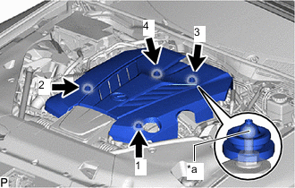
*a Tip (Sphere) Attach the 4 clips in the order shown in the illustration to install the V-bank cover sub-assembly.
Note
-
Securely attach the clips.
-
If the clips are forcibly attached or struck with an object, they may be damaged.
-
Do not apply any oil to the tips (sphere).
-
-