BRAKE BOOSTER(for RHD) REMOVAL
CAUTION / NOTICE / HINT
The necessary procedures (adjustment, calibration, initialization, or registration) that must be performed after parts are removed, installed, or replaced during brake booster assembly removal/installation are shown below.
| Replaced Part or Performed Procedure | Necessary Procedure | Effect/Inoperative Function when Necessary Procedure not Performed | Link |
|---|---|---|---|
| Battery terminal is disconnected/reconnected | Memorize steering angle neutral point | LKA/LDA System | |
| Intelligent clearance sonar system | |||
| Pre-Crash Safety System | |||
| Lighting System (EXT)
|
|||
| Adaptive High Beam System | |||
| Parking Assist Monitor System (w/ Parallel Parking Assist Function) | |||
| Parking Assist Monitor System (w/o Parallel Parking Assist Function) | |||
| Panoramic View Monitor System | |||
| Drive the vehicle until stop and start control is permitted (approximately 15 to 60 minutes) | Stop and start system | ||
| Initialize back door lock | Power door lock control system | ||
| Reset back door close position | Power back door system |
CAUTION / NOTICE / HINT
Note
Make sure to release vacuum from the brake booster assembly before removing the brake master cylinder sub-assembly from the brake booster assembly.
PROCEDURE
-
PRECAUTION
Note
After turning the engine switch off, waiting time may be required before disconnecting the cable from the negative (-) battery terminal. Therefore, make sure to read the disconnecting the cable from the negative (-) battery terminal notices before proceeding with work.
-
RECOVER REFRIGERANT FROM REFRIGERATION SYSTEM
for HFC-134a (R134a): Click here
for HFO-1234yf (R1234yf): Click here
-
DISCONNECT CABLE FROM NEGATIVE BATTERY TERMINAL
Note
When disconnecting the cable, some systems need to be initialized after the cable is reconnected.
-
REMOVE FUEL PUMP ASSEMBLY (for 2GR-FKS)
-
REMOVE BRAKE MASTER CYLINDER SUB-ASSEMBLY WITH WAY
-
REMOVE FRONT DOOR SCUFF PLATE RH
Tech Tips
Use the same procedure as for the LH side.
w/o Rear No. 2 Seat: Click here
w/ Rear No. 2 Seat: Click here
-
REMOVE COWL SIDE TRIM BOARD RH
-
REMOVE NO. 1 INSTRUMENT PANEL UNDER COVER SUB-ASSEMBLY
-
REMOVE NO. 1 ENGINE COVER SUB-ASSEMBLY (for 8AR-FTS)
-
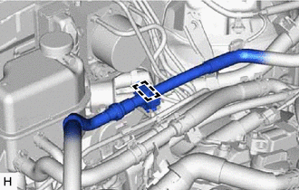
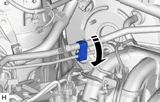
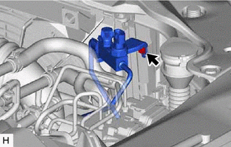
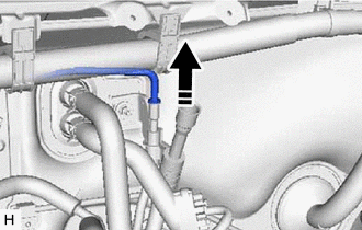
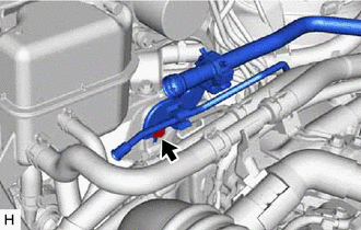
DISCONNECT CHECK VALVE TO BRAKE BOOSTER HOSE (for 8AR-FTS)
-
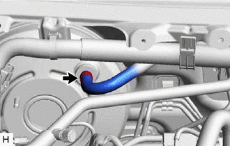
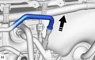
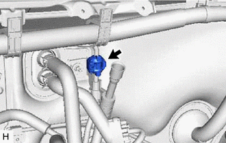
Slide the clip and disconnect the check valve to brake booster hose from the brake booster assembly.
-
-
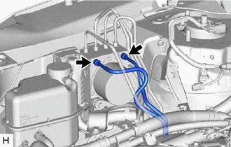
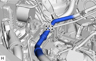
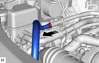
DISCONNECT UNION TO CHECK VALVE HOSE (for 2GR-FKS)
-
w/o Rear Air Conditioning System:
-
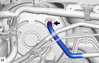
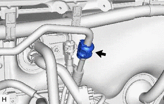
Slide the clip and disconnect the union to check valve hose from the brake booster assembly.
-
-
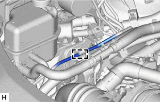
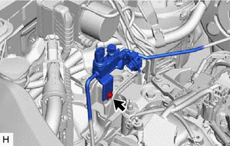
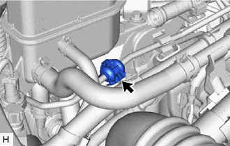
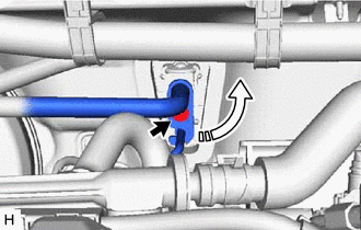
w/ Rear Air Conditioning System:
-
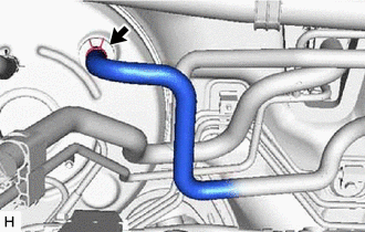
Slide the clip and disconnect the union to check valve hose from the brake booster assembly.
-
-
-
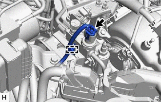
SEPARATE ENGINE ROOM MAIN WIRE
-
for 8AR-FTS:
-
Disconnect the connector from the vacuum sensor assembly.
-
-
for 2GR-FKS:
-
Disconnect the connector from the vacuum warning switch assembly.
-
-
Disengage the 8 clamps to separate the engine room main wire.
-
-
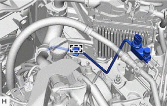
SEPARATE BRAKE LINE
-
Using a union nut wrench, disconnect the front No. 6 brake tube and front No. 7 brake tube from the brake actuator assembly.
Note
-
Do not kink or damage the brake lines.
-
Do not allow any foreign matter such as dirt or dust to enter the brake line from the connecting parts.
-
-
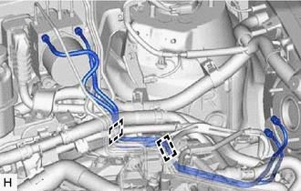
Disengage the 2 clamps and remove the front No. 6 brake tube and front No. 7 brake tube.
Note
-
Do not damage the 2 clamps.
-
Do not kink or damage the brake lines.
-
-
-
SEPARATE SUCTION PIPE SUB-ASSEMBLY (w/o Sub-cool Accelerator)
-
for 8AR-FTS:
-
Disengage the clamp from the suction pipe sub-assembly.
-
Disengage the clamp to separate the suction pipe sub-assembly.
Note
-
Do not deform the refrigerant lines.
-
Do not damage the clamp.
-
-
-
for 2GR-FKS:
-
Disengage the clamp from the suction pipe sub-assembly.
-
Disengage the clamp to separate the suction pipe sub-assembly.
Note
-
Do not deform the refrigerant lines.
-
Do not damage the clamp.
-
-
-
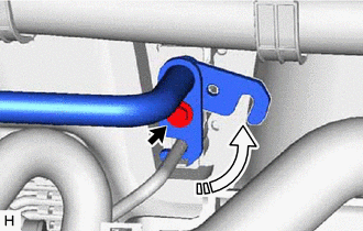
Remove the bolt and rotate the hook connector.
-
Disconnect the suction pipe sub-assembly from the air conditioning unit assembly.
-
Remove the O-ring from the suction pipe sub-assembly.
Note
Seal the openings of the disconnected parts using vinyl tape to prevent entry of moisture and foreign matter.
-
-
SEPARATE AIR CONDITIONER TUBE AND ACCESSORY ASSEMBLY (w/o Sub-cool Accelerator)
-
for 8AR-FTS:
-
Disengage the clamp to separate the air conditioner tube and accessory assembly from the piping clamp.
Note
-
Do not deform the refrigerant lines.
-
Do not damage the clamp.
-
-
Remove the bolt and separate the air conditioner tube and accessory assembly.
Note
Do not deform the refrigerant lines.
-
-
for 2GR-FKS:
-
Disconnect the connector from the air conditioner tube and accessory assembly.
-
Disengage the clamp.
-
Remove the bolt and separate the air conditioner tube and accessory assembly.
Note
Do not deform the refrigerant lines.
-
Disengage the clamp to separate the air conditioner tube and accessory assembly.
Note
-
Do not deform the refrigerant lines.
-
Do not damage the clamp.
-
-
-
Disconnect the air conditioner tube and accessory assembly from the air conditioning unit assembly.
-
Remove the O-ring from the air conditioner tube and accessory assembly.
Note
Seal the openings of the disconnected parts using vinyl tape to prevent entry of moisture and foreign matter.
-
-
DISCONNECT SUCTION PIPE SUB-ASSEMBLY (w/o Sub-cool Accelerator)
-
for 2GR-FKS with Rear Air Conditioning System:
-
Remove the piping clamp.
-
Disconnect the suction pipe sub-assembly from the air conditioning hose and accessory.
Note
Do not deform the refrigerant lines.
-
Remove the 2 O-rings from the suction pipe sub-assembly.
Note
Seal the openings of the disconnected parts using vinyl tape to prevent entry of moisture and foreign matter.
-
-
-
DISCONNECT AIR CONDITIONER TUBE AND ACCESSORY ASSEMBLY (w/o Sub-cool Accelerator)
-
for 2GR-FKS with Rear Air Conditioning System:
-
Remove the piping clamp.
-
Disconnect the air conditioner tube and accessory assembly from the air conditioning hose and accessory.
Note
Do not deform the refrigerant lines.
-
Remove the 2 O-rings from the air conditioner tube and accessory assembly.
Note
Seal the openings of the disconnected parts using vinyl tape to prevent entry of moisture and foreign matter.
-
-
-
SEPARATE SUCTION HOSE SUB-ASSEMBLY (w/ Sub-cool Accelerator)
-
Separate the suction hose sub-assembly from the No. 2 air conditioner tube and accessory assembly.
Note
Do not deform the refrigerant lines.
-
Remove the 2 O-rings and piping clamp from the suction hose sub-assembly.
Note
Seal the openings of the disconnected parts using vinyl tape to prevent entry of moisture and foreign matter.
-
-
SEPARATE AIR CONDITIONER TUBE AND ACCESSORY ASSEMBLY (w/ Sub-cool Accelerator)
-
Remove the piping clamp.
-
Remove the bolt and separate the air conditioner tube and accessory assembly.
Note
Do not deform the refrigerant lines.
-
Disconnect the air conditioner tube and accessory assembly from the No. 2 air conditioner tube and accessory assembly.
-
Remove the 2 O-rings from the air conditioner tube and accessory assembly.
Note
Seal the openings of the disconnected parts using vinyl tape to prevent entry of moisture and foreign matter.
-
-
REMOVE NO. 2 AIR CONDITIONER TUBE AND ACCESSORY ASSEMBLY (w/ Sub-cool Accelerator)
-
Remove the bolt and separate the No. 2 air conditioner tube and accessory assembly.
Note
Do not deform the refrigerant lines.
-
Remove the bolt and rotate the hook connector.
-
Remove the No. 2 air conditioner tube and accessory assembly from the air conditioning unit assembly.
Note
Do not deform the refrigerant lines.
-
Remove the 2 O-rings from the No. 2 air conditioner tube and accessory assembly.
Note
Seal the openings of the disconnected parts using vinyl tape to prevent entry of moisture and foreign matter.
-
-
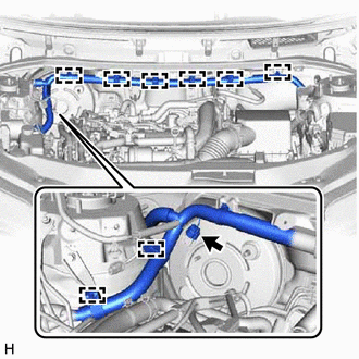
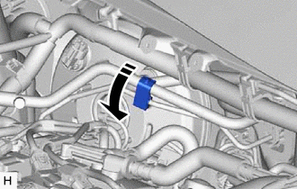
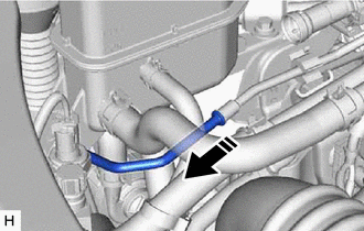
REMOVE NO. 2 VENTILATION HOSE (for 2GR-FKS)
-
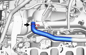
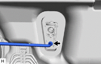
Slide the clip and disconnect the No. 2 ventilation hose to remove it from the cylinder head cover sub-assembly.
-
-
DISCONNECT FUEL TUBE SUB-ASSEMBLY (for 2GR-FKS)
-
REMOVE FUEL DELIVERY PIPE SUB-ASSEMBLY (for 2GR-FKS)
-
REMOVE NO. 1 DELIVERY PIPE SPACER (for 2GR-FKS)
-
REMOVE INJECTOR VIBRATION INSULATOR (for 2GR-FKS)
-
SEPARATE ENGINE WIRE (for 2GR-FKS)
-
Disengage the 4 clamps and disconnect the 8 connectors.
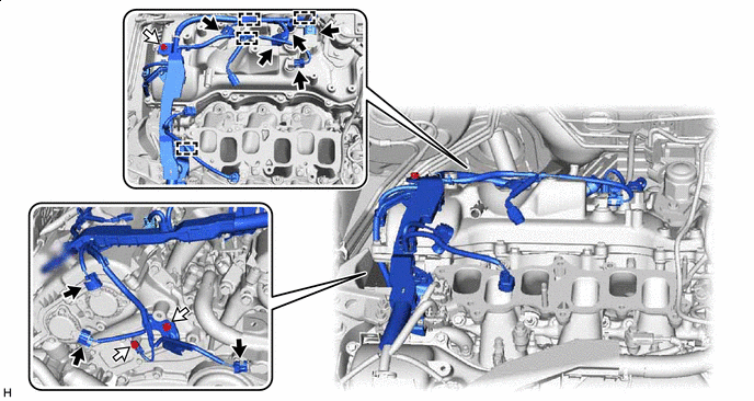

Connector 
Bolt -
Remove the 3 bolts to separate the engine wire.
-
-
REMOVE IGNITION COIL ASSEMBLY (for 2GR-FKS)
-
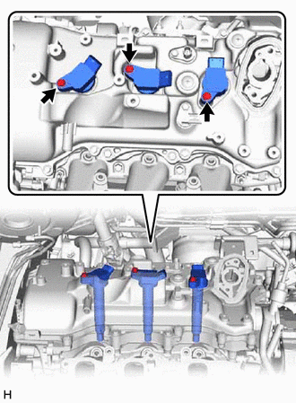
Remove the 3 bolts and 3 ignition coil assemblies.
-
-
REMOVE VVT SENSOR (for 2GR-FKS)
for Intake Side of Bank 1: Click here
-
REMOVE VVT SENSOR (for 2GR-FKS)
for Exhaust Side of Bank 1: Click here
-
REMOVE CYLINDER HEAD COVER SUB-ASSEMBLY (for 2GR-FKS)
-
REMOVE BRAKE PEDAL RETURN SPRING
-
LOOSEN LOCK NUT
-
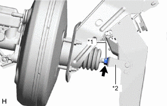
*1 Lock Nut *2 Brake Master Cylinder Push Rod Clevis Loosen the lock nut of the brake master cylinder push rod clevis.
-
-
REMOVE PUSH ROD PIN
-
REMOVE BRAKE BOOSTER ASSEMBLY
-
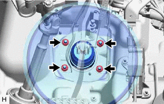
Remove the 4 nuts and push the brake booster assembly toward the engine compartment.
Note
Do not apply excessive force to the refrigerant lines.
-
Remove the brake master cylinder push rod clevis and lock nut from the brake booster assembly.
-
Remove the brake booster assembly from the vehicle body.
Note
Do not apply excessive force to the refrigerant lines.
-
-
REMOVE BRAKE BOOSTER GASKET