FRONT SUSPENSION MEMBER REMOVAL

CAUTION / NOTICE / HINT
The necessary procedures (adjustment, calibration, initialization, or registration) that must be performed after parts are removed and installed, or replaced during front frame assembly removal/installation are shown below.
| Replaced Part or Performed Procedure | Necessary Procedure | Effect/Inoperative Function when Necessary Procedure not Performed | Link | |
|---|---|---|---|---|
| Battery terminal is disconnected/reconnected | Memorize steering angle neutral point | LKA/LDA System | ||
| Intelligent clearance sonar system*3 | ||||
| Pre-crash safety system | ||||
| Lighting system (EXT)
|
||||
| Adaptive high beam system | ||||
| Drive the vehicle until stop and start control is permitted (approximately 15 to 60 minutes) | Stop and start system | |||
| Memorize steering angle neutral point | Parking Assist Monitor System (w/ Parallel Parking Assist Function) | |||
| Parking Assist Monitor System (w/o Parallel Parking Assist Function) | ||||
| Panoramic view monitor system | ||||
| Initialize back door lock | Power door lock control system | |||
| Reset back door close position | Power back door system | |||
| Replacement of ECM | Perform Vehicle Identification Number (VIN) or frame number registration |
|
for 8AR-FTS: Click here for 2GR-FKS (w/ Canister Pump Module): Click here for 2GR-FKS (w/o Canister Pump Module): Click here |
|
| ECU Communication ID Registration (Immobiliser system) | Engine start function | See Service Bulletin for the registration method. | ||
|
Inspection After Repair |
|
for 8AR-FTS: Click here for 2GR-FKS (w/ Canister Pump Module): Click here for 2GR-FKS (w/o Canister Pump Module): Click here |
|
| Replacement of starter assembly*1 Note When the starter assembly is replaced, "ST relay" and "ST NO. 2 relay" must be also replaced. |
Clear Number of Starter Operations | Stop and start system | ||
| Replacement of battery*1 |
|
|||
|
Bleed the oil pump assembly with motor (continuously variable transaxle assembly) | |||
| Replacement of automatic transaxle assembly | Perform the following procedures in the order shown:
|
|
for Initialization (U661E): Click here for Registration (U661E): Click here for Initialization (U661F): Click here for Registration (U661F): Click here for Initialization (U881E): Click here for Registration (U881E): Click here for Initialization (U881F): Click here for Registration (U881F): Click here |
|
| Replacement of ECM (If possible, read the transaxle compensation code from the previous ECM) |
Possible to read transaxle compensation code | Perform the following procedures in the order shown:
|
||
| Impossible to read transaxle compensation code | Perform the following procedures in the order shown:
|
|||
| Suspension, tires, etc. (The vehicle height changes because of suspension or tire replacement) |
|
|
||
| Rear television camera assembly optical axis (Back camera position setting) | Parking assist monitor system (w/ Parallel Parking Assist Function) | for Initialization: Click here for Calibration: Click here |
||
| Parking assist monitor system (w/o Parallel Parking Assist Function) | for Initialization: Click here for Calibration: Click here |
|||
|
Panoramic view monitor system | for Initialization: Click here for Calibration: Click here |
||
| Initialize headlight ECU sub-assembly LH |
|
|||
| Front wheel alignment adjustment |
|
|
||
*2: w/ TFT Meter Type
*3: When performing learning using the GTS.
Click here Click here
PROCEDURE
-
REMOVE FRONT FRAME ASSEMBLY
for 2GR-FKS: Click here
for 8AR-FTS: Click here
-
REMOVE FRONT ENGINE MOUNTING INSULATOR
for 2GR-FKS: Click here
for 8AR-FTS: Click here
-
REMOVE REAR ENGINE MOUNTING INSULATOR
for 2GR-FKS: Click here
for 8AR-FTS: Click here
-
REMOVE FRONT LOWER NO. 1 SUSPENSION ARM SUB-ASSEMBLY LH
-
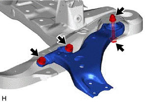
Remove the 3 bolts, nut and front lower No. 1 suspension arm sub-assembly LH from the front frame assembly.
Note
Because the nut has its own stopper, do not turn the nut. Loosen the bolt with the nut secured.
-
-
REMOVE FRONT LOWER NO. 1 SUSPENSION ARM SUB-ASSEMBLY RH
Tech Tips
Perform the same procedure as for the LH side.
-
REMOVE FRONT NO. 2 SUSPENSION MEMBER DYNAMIC DAMPER (for 2GR-FKS 2WD)
-
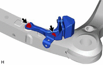
Remove the 2 bolts and front No. 2 suspension member dynamic damper from the front frame assembly.
-
-
REMOVE FRONT SUSPENSION MEMBER DUMPER PLATE (except 2GR-FKS AWD)
-
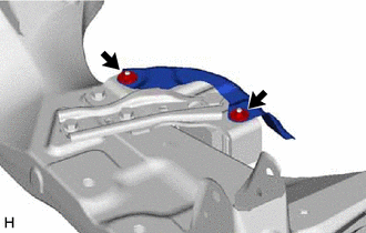
Remove the 2 nuts and front suspension member damper plate from the front suspension member dynamic damper.
-
-
REMOVE FRONT SUSPENSION MEMBER DYNAMIC DAMPER (except 2GR-FKS AWD)
-
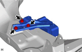
Remove the 3 bolts and front suspension member dynamic damper from the front frame assembly.
-
-
REMOVE FRONT SUSPENSION MEMBER BODY MOUNTING FRONT STOPPER
-
Remove the 2 front suspension member body mounting front stoppers from the front frame assembly.
-
-
REMOVE FRONT SUSPENSION MEMBER BODY MOUNTING REAR STOPPER
-
Remove the 2 front suspension member body mounting rear stoppers from the front frame assembly.
-
-
REMOVE FRONT SUSPENSION MEMBER BODY MOUNTING FRONT CUSHION LH
-
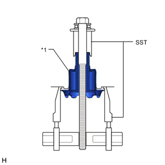
*1 Front Suspension Member Body Mounting Front Cushion LH Install SST as shown in the illustration.
- SST
- 09830-10010 ( 09830-01010, 09830-01040, 09830-01050 )
- 09950-40011 ( 09951-04020, 09952-04010, 09954-04010, 09955-04011, 09958-04011 )
-
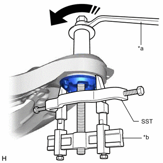
*a Turn *b Hold Turn the SST center bolt in the direction shown by the arrow in the illustration to create a clearance between the front suspension member body mounting front cushion LH and the front frame assembly.
-
While applying penetrating lubricant to the front suspension member body mounting front cushion LH through the clearance, gradually remove the front suspension member body mounting front cushion LH.
Note
-
Make sure that the claws of SST are securely engaged to the mounting cushion.
-
Tighten SST slowly and evenly.
-
Be careful as the mounting cushion may fly out.
-
The mounting cushion cannot be reused.
-
-
-
REMOVE FRONT SUSPENSION MEMBER BODY MOUNTING FRONT CUSHION
Tech Tips
Perform the same procedure as for the front suspension member body mounting front cushion LH.
-
REMOVE FRONT SUSPENSION MEMBER BODY MOUNTING REAR CUSHION LH
-
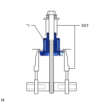
*1 Front Suspension Member Body Mounting Rear Cushion LH Install SST as shown in the illustration.
- SST
- 09830-10010 ( 09830-01010, 09830-01040, 09830-01050 )
- 09950-40011 ( 09951-04020, 09952-04010, 09954-04010, 09955-04011, 09958-04011 )
-
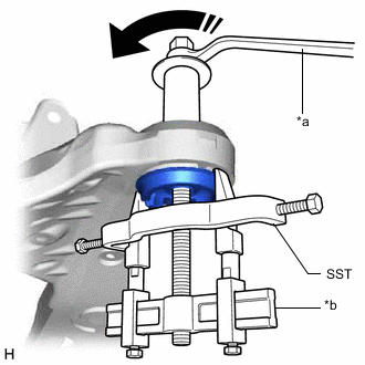
*a Turn *b Hold Turn the SST center bolt in the direction shown by the arrow in the illustration to create a clearance between the front suspension member body mounting rear cushion LH and the front frame assembly.
-
While applying penetrating lubricant to the front suspension member body mounting rear cushion LH through the clearance, gradually remove the front suspension member body mounting rear cushion LH.
Note
-
Make sure that the claws of SST are securely engaged to the mounting cushion.
-
Tighten SST slowly and evenly.
-
Be careful as the mounting cushion may fly out.
-
The mounting cushion cannot be reused.
-
-
-
REMOVE FRONT SUSPENSION MEMBER BODY MOUNTING REAR CUSHION
Tech Tips
Perform the same procedure as for the front suspension member body mounting rear cushion LH.
-
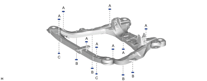
REMOVE HOLE PLUG
-
for Type A:
-
Remove the 14 hole plugs from the front frame assembly.
Tech Tips
There are 3 different shapes of hole plug.
-
-
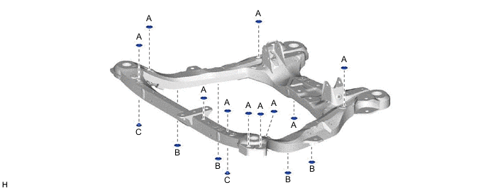
for Type B:
-
Remove the 16 hole plugs from the front frame assembly.
Tech Tips
There are 3 different shapes of hole plug.
-
-