AUTOMATIC TRANSMISSION ASSEMBLY(for V35A-FTS) REMOVAL
CAUTION / NOTICE / HINT
The necessary procedures (adjustment, calibration, initialization, or registration) that must be performed after parts are removed, installed, or replaced during the automatic transmission assembly removal/installation are shown below.
| Replacement Part or Procedure | Necessary Procedure | Effect/Inoperative when not Performed | Link |
|---|---|---|---|
| Disconnect cable from negative battery terminal | Drive the vehicle until stop and start control is permitted (approximately 5 to 60 minutes) | Stop and start system | |
| Memorize steering angle neutral point | LKA/LDA system | ||
| Parking support brake system*1 | |||
| Pre-collision system | |||
| Adaptive high beam system | |||
Lighting system (EXT) |
|||
| Variable gear ratio steering system | |||
| Parking assist monitor system | |||
| Panoramic view monitor system | |||
| Initialize rear door sunshade system | Rear door sunshade system | ||
| Initialize power trunk lid system | Power trunk lid system | ||
|
Inspection after repair |
|
w/ Canister Pump Module: Click here w/o Canister Pump Module: Click here |
| Engine assembly | Inspection after repair |
|
w/ Canister Pump Module: Click here w/o Canister Pump Module: Click here |
|
|
||
| w/ Stop and Start System: Starter assembly Note When the starter assembly is replaced, "ST NO. 1 relay" and "ST NO. 2 relay" must be also replaced. |
Clear number of starter operations | Stop and start system | |
| Automatic transmission assembly |
|
|
for Initialization: Click here for Registration: Click here |
| Automatic transmission fluid | ATF thermal degradation estimate reset | The value of the Data List item "ATF Thermal Degradation Estimate" is not estimated correctly. | |
| Parts between the steering wheel and tires have been removed/installed, replaced or adjusted | Perform actuator angle neutral point calibration and initialization |
|
|
| Front bumper assembly (Including removal and installation) |
|
Parking support brake system | |
| Front television camera view adjustment | Panoramic view monitor system | ||
| Suspension, tires, etc. |
|
Parking support brake system | |
|
Panoramic view monitor system | ||
| Rear television camera assembly optical axis (Back camera position setting) | Parking assist monitor system |
Click here Click here
*2: New automatic transmission's compensation code.
Note
After the engine switch is turned off, the radio receiver assembly records various types of memory and settings. As a result, after turning the engine switch off, be sure to wait for the time specified in the following table before disconnecting the cable from the negative (-) battery terminal.
| System Name | See Procedure |
|---|---|
| Vehicle enrolled in lexus enform system or safety connect system | 6 minutes |
| Vehicle not enrolled in lexus enform system and safety connect system | 1 minute |
CAUTION:
-
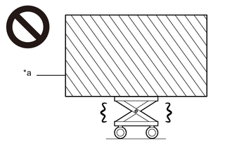
*a Heavy object exceeding the capacity of the engine lifter Because the weight of the engine with transmission assembly is extremely heavy, make sure to follow the work procedures described in the repair manual.
-
If work is not performed according to the procedures described in the repair manual, there is a danger that the engine lifter could drop and components could fall down.
-
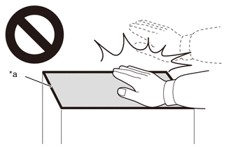
*a High temperature areas Do not touch the engine or exhaust manifold sub-assembly when they are hot.
-
Touching the engine or exhaust manifold sub-assembly when they are hot could result in burns.
-
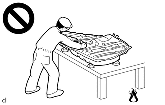
Never perform work on fuel system components near any possible ignition sources.
-
Vaporized fuel could ignite, resulting in a serious accident.
-
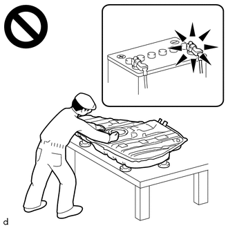
Do not perform work on fuel system components without first disconnecting the cable from the negative (-) battery terminal.
-
Sparks could cause vaporized fuel to ignite, resulting in a serious accident.
Note
This procedure includes the removal of small-head bolts. Refer to Small-Head Bolts of Basic Repair Hint to identify the small-head bolts.
PROCEDURE
-
PRECAUTION
Note
After turning the engine switch off, waiting time may be required before disconnecting the cable from the negative (-) battery terminal. Therefore, make sure to read the disconnecting the cable from the negative (-) battery terminal notices before proceeding with work.
-
REMOVE ENGINE ASSEMBLY WITH TRANSMISSION
-
REMOVE AIR FUEL RATIO SENSOR (for Bank 1 Sensor 1)
-
REMOVE AIR FUEL RATIO SENSOR (for Bank 2 Sensor 1)
-
REMOVE AIR FUEL RATIO SENSOR (for Bank 1 Sensor 2)
-
REMOVE AIR FUEL RATIO SENSOR (for Bank 2 Sensor 2)
-
REMOVE NO. 4 TURBO INSULATOR
-
REMOVE NO. 2 TURBO INSULATOR
-
REMOVE CONVERTER ASSEMBLY LH
-
REMOVE CONVERTER ASSEMBLY RH
-
DISCONNECT NO. 2 ENGINE WIRE
-
w/ Stop and Start System:
-
w/o Stop and Start System:
-
-
REMOVE FLYWHEEL HOUSING SIDE STAY
-
w/ Stop and Start System:
-
w/o Stop and Start System:
-
-
REMOVE STARTER COVER
-
w/ Stop and Start System:
-
w/o Stop and Start System:
-
-
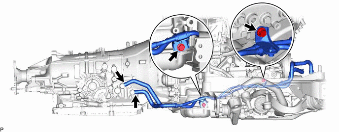
DISCONNECT OIL COOLER TUBE WITH OIL COOLER HOSE
-
Slide the 2 hose clips and disconnect the 2 oil cooler hoses from the automatic transmission assembly.
-
Remove the 2 bolts and disconnect the oil cooler tube from the engine assembly and automatic transmission assembly.
Tech Tips
When removing the automatic transmission assembly, hold the oil cooler tube in a position so that the oil cooler tube and automatic transmission assembly do not interfere with one another.
-
-
REMOVE STARTER ASSEMBLY
-
w/ Stop and Start System:
-
w/o Stop and Start System:
-
-
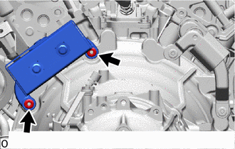
REMOVE FLYWHEEL HOUSING SIDE COVER
-
Remove the flywheel housing side cover from the engine assembly.
-
-
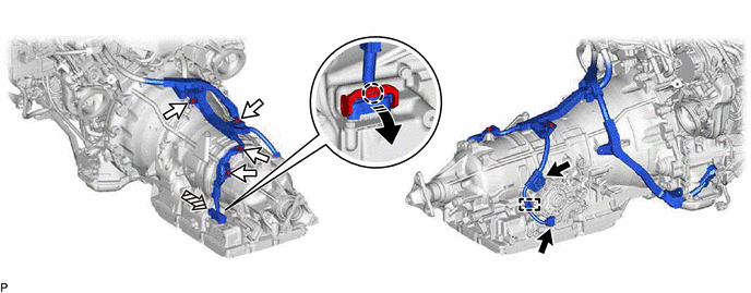
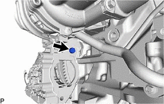
DISCONNECT WIRE HARNESS
-
Disconnect the transmission wire connector.

Wire Harness Connector 
Bolt 
Transmission Wire Connector 
Pull Down the Lever Tech Tips
Disconnect the claw, pull down the lever, and then disconnect the transmission wire connector
-
Disconnect the 2 wire harness connectors and wire harness clamp.
-
Remove the 4 bolts and disconnect the wire harness from the automatic transmission assembly.
-
-
REMOVE DRIVE PLATE AND TORQUE CONVERTER SETTING BOLT
-
Remove the crankshaft damper sub-assembly.
-
Remove the 6 drive plate and torque converter setting bolts from the drive plate and ring gear sub-assembly.
Tech Tips
Turn the crankshaft to a position where the drive plate and torque converter setting bolts can be removed, and remove the drive plate and torque converter setting bolts while securing the crankshaft pulley bolt with a wrench.
-
-
REMOVE ENGINE REAR MOUNTING MEMBER
-
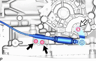
Bolt Nut and Spring Washer Remove the nut, spring washer and 2 bolts and disconnect the throttle link connecting rod assembly from the shift control actuator assembly.
-
Remove the 3 nuts and engine rear mounting member.
-
-
REMOVE REAR ENGINE MOUNTING INSULATOR
-
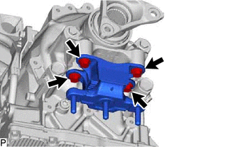
Remove the 4 bolts and rear engine mounting insulator.
-
-
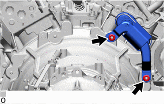
REMOVE TRANSMISSION DYNAMIC DAMPER ASSEMBLY LH (for LHD)
-
Remove the 2 nuts and transmission dynamic damper assembly LH from the automatic transmission assembly.
-
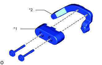
Remove the transmission dynamic damper insulator from the transmission dynamic damper.
-
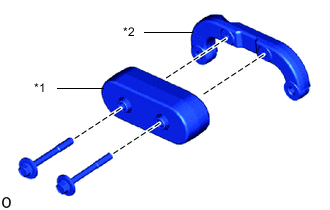
*1 Transmission Dynamic Damper *2 Transmission Dynamic Damper Bracket LH Remove the 2 bolts and transmission dynamic damper from the transmission dynamic damper bracket LH.
-
-
REMOVE TRANSMISSION DYNAMIC DAMPER ASSEMBLY RH (for LHD)
-
Remove the 2 nuts and transmission dynamic damper assembly RH from the automatic transmission assembly.
-
Remove the transmission dynamic damper insulator from the transmission dynamic damper.
-
*1 Transmission Dynamic Damper *2 Transmission Dynamic Damper Bracket RH Remove the 2 bolts and transmission dynamic damper from the transmission dynamic damper bracket RH.
-
-
REMOVE TRANSMISSION DYNAMIC DAMPER ASSEMBLY RH (for RHD)
-
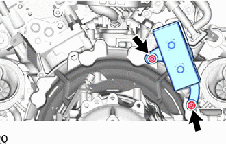
Remove the 2 nuts and transmission dynamic damper assembly RH from the automatic transmission assembly.
-
Remove the transmission dynamic damper insulator from the transmission dynamic damper.
-
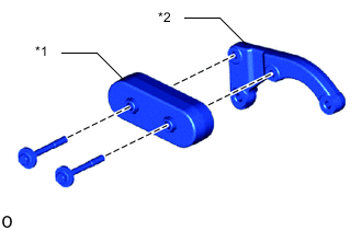
*1 Transmission Dynamic Damper *2 Transmission Dynamic Damper Bracket RH Remove the 2 bolts and transmission dynamic damper from the transmission dynamic damper bracket RH.
-
-
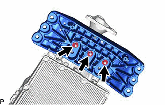
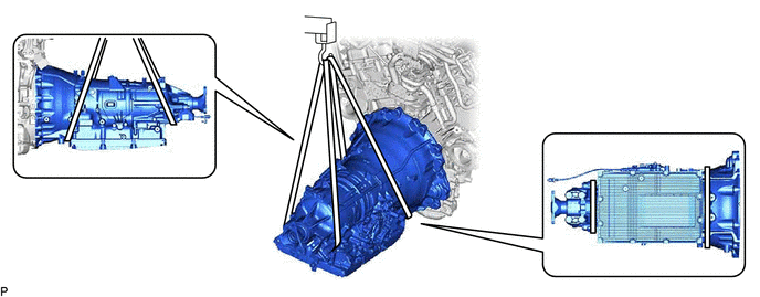
REMOVE AUTOMATIC TRANSMISSION ASSEMBLY
-
Using a rope or equivalent, support the automatic transmission assembly at the positions shown in the illustration.
CAUTION:
Secure the engine assembly to the engine lifter using a belt, etc. to prevent it from falling.
-
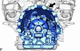
Remove the stud bolt from the engine assembly.
-
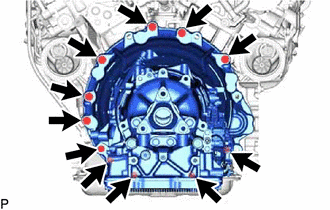
Remove the 11 bolts and automatic transmission assembly.
CAUTION:
-
Do not raise the automatic transmission assembly more than necessary.
-
Make sure to confirm the center of the gravity of the automatic transmission assembly when supporting it.
Note
-
Do not use excessive force to pry out the automatic transmission assembly when separating it from the engine assembly to prevent the knock pins from being damaged.
-
When removing the automatic transmission assembly, make sure that the oil cooler tube does not become damaged.
-
Do not allow the wooden blocks or equivalent to contact the transmission oil pan assembly when supporting the automatic transmission assembly, as the transmission oil pan assembly may be deformed as a result.
-
-
-
REMOVE TORQUE CONVERTER ASSEMBLY
-
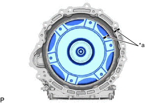
*a Matchmark Put matchmarks on the automatic transmission assembly and torque converter assembly.
-
Remove the torque converter assembly from the automatic transmission assembly.
-
-
INSPECT TORQUE CONVERTER ASSEMBLY