ECD SYSTEM (w/o EGR Cooler), Diagnostic DTC:P2009, P2010
| DTC Code | DTC Name |
|---|---|
| P2009 | Intake Manifold Runner Control Circuit Low (Bank 1) |
| P2010 | Intake Manifold Runner Control Circuit High (Bank 1) |
DESCRIPTION
Refer to DTC P2006 Click here.
| DTC No. | DTC Detection Condition | Trouble Area |
|---|---|---|
| P2009 | Open in VSV for swirl control valve circuit for 0.5 seconds (2 trip detection logic) |
|
| P2010 | Short in VSV for swirl control valve circuit for 0.5 seconds (2 trip detection logic) |
|
WIRING DIAGRAM
Refer to DTC P2006 Click here.
INSPECTION PROCEDURE
Note
After replacing the ECM, the new ECM needs registration Click here and initialization Click here.
Tech Tips
Read freeze frame data using the intelligent tester. Freeze frame data records the engine conditions when a malfunction is detected. When troubleshooting, freeze frame data can help determine if the vehicle was moving or stationary, if the engine was warmed up or not, and other data from the time the malfunction occurred.
PROCEDURE
-
PERFORM ACTIVE TEST USING INTELLIGENT TESTER (ACTIVATE THE VSV FOR SWIRL CONTROL VALVE)
-
Connect the intelligent tester to the DLC3.
-
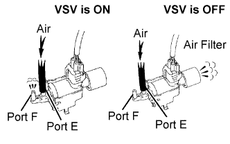
Disconnect the vacuum hoses from the VSV for swirl control valve.
-
Turn the ignition switch ON and turn the tester ON.
-
Enter the following menus: Powertrain / Engine / Active Test / Activate the VSV for Swirl Control Valve.
-
Check the VSV operation when it is operated using the intelligent tester.
OK Tester Operation Specified Condition VSV ON Air from port E flows out through port F VSV OFF Air from port E flows out through air filter
OK 
CHECK FOR INTERMITTENT PROBLEMS Click here
NG 
-
-
INSPECT VACUUM SWITCHING VALVE FOR SWIRL CONTROL VALVE (RESISTANCE)
-
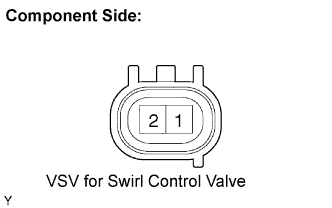
Disconnect the S9 VSV for swirl control valve connector.
-
Measure the resistance of the VSV for swirl control valve.
Standard resistance Tester Connection Condition Specified Condition 1 - 2 20°C (68°F) 33 to 39 Ω
NG
REPLACE VACUUM CONTROL VALVE SET
OK
-
-
INSPECT VACUUM SWITCHING VALVE FOR SWIRL CONTROL VALVE (POWER SOURCE VOLTAGE)
-
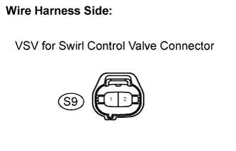
Disconnect the S9 VSV for swirl control valve connector.
-
Turn the ignition switch ON.
-
Measure the voltage of the wire harness side connector and body ground.
Standard voltage Tester Connection Specified Condition S9-2 - Body ground 11 to 14 V
OK 
CHECK HARNESS AND CONNECTOR (VACUUM SWITCHING VALVE FOR SWIRL CONTROL VALVE - ECM) Click here
NG
-
-
CHECK HARNESS AND CONNECTOR (VSV FOR SWIRL CONTROL VALVE - NO. 1 INTEGRATION RELAY)
-
Remove the No. 1 integration relay from the engine room junction block Click here.
-
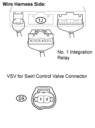
Disconnect the 1J No. 1 integration relay connector.
-
Disconnect the S9 VSV for swirl control valve connector.
-
Measure the resistance of the wire harness side connectors.
Standard resistance (Check for open) Tester Connection Specified Condition 1J-5 - S9-2 Below 1 Ω Standard resistance (Check for short) Tester Connection Specified Condition 1J-5 or S9-2 - Body ground 10 kΩ or higher
NG
REPAIR OR REPLACE HARNESS OR CONNECTOR
OK 
INSPECT ECM POWER SOURCE CIRCUIT Click here
-
-
CHECK HARNESS AND CONNECTOR (VACUUM SWITCHING VALVE FOR SWIRL CONTROL VALVE - ECM)
-
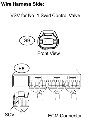
Disconnect the S9 VSV for swirl control valve connector.
-
Disconnect the E8 ECM connector.
-
Measure the resistance of the wire harness side connector.
Standard resistance (Check for open) Tester Connection Specified Condition S9-1 - SCV (E8-15) Below 1 Ω Standard resistance (Check for short) Tester Connection Specified Condition S9-1 or SCV (E8-15) - Body ground 10 kΩ or higher
NG
REPAIR OR REPLACE HARNESS OR CONNECTOR
OK
REPLACE ECM Click here
-