ECD SYSTEM (w/o EGR Cooler), Diagnostic DTC:P1271, P1272
| DTC Code | DTC Name |
|---|---|
| P1271 | Fuel Regulator Circuit Malfunction (EDU Drive) |
| P1272 | Fuel Pressure Regulator Malfunction |
DESCRIPTION
Tech Tips
-
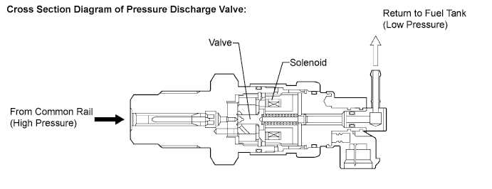
For more information on the pressure discharge valve and the common rail system Click here.
-
For more information on the injection driver (EDU) Click here.
-
If P1271 and/or P1272 is present, refer to the DTC chart for the fuel system Click here.
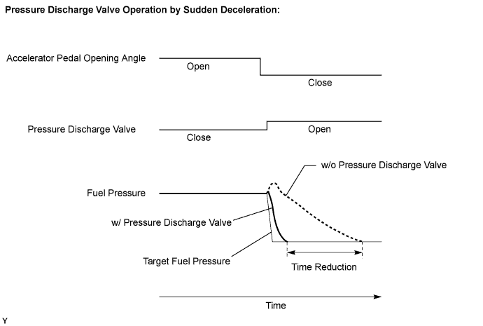
The ECM controls the internal fuel pressure of the common rail by opening and closing the pressure discharge valve. When sudden deceleration occurs, the internal fuel pressure will temporarily become higher than usual and combustion noise may result. Therefore the ECM will open the valve temporarily to discharge the excess pressure inside the common rail. Also, the pressure discharge valve opens when the ignition switch is turned OFF to allow prompt discharge of the common rail internal pressure.
| DTC No. | DTC Detection Condition | Trouble Area |
|---|---|---|
| P1271 | Open or short in pressure discharge valve circuit. There is no valve opening confirmation (IJF) signal from EDU to ECM despite the ECM sending valve opening command (PRD) signal after the engine is started. (1 trip detection logic) |
|
| P1272 | Pressure discharge valve closed malfunction. Actual pressure decreasing rate deviates from the simulated pressure decreasing rate after the ignition switch is turned OFF. (2 trip detection logic) |
|
Tech Tips
After confirming DTC P1271 and/or P1272, check the fuel pressure inside the common rail in the Powertrain / Engine and ECT / Data List / Fuel Press using the intelligent tester.
| Reference | ||||||
|---|---|---|---|---|---|---|
|
MONITOR DESCRIPTION
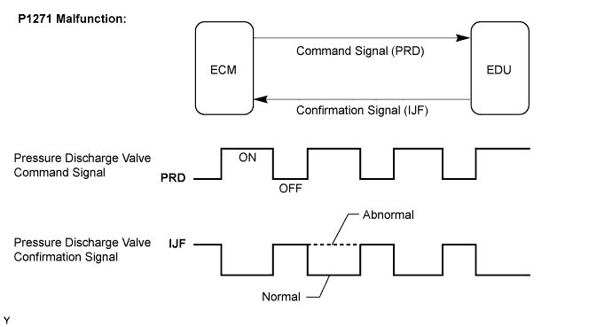
P1271 (Open or short in pressure discharge valve circuit):This DTC will be set if there is no valve opening confirmation (IJF) signal sent from the EDU to the ECM even though the ECM has commanded the EDU to open the pressure discharge valve. This DTC refers to an open or short circuit malfunction of the pressure discharge valve circuit, not a malfunction that includes a valve that is stuck open or closed.
The EDU monitors the current supplied to the pressure discharge valve to verify that the current flows into the valve. If the current exceeds the specified level, the EDU determines that the IJF signal is low. If this DTC is present, the ECM enters the fail-safe mode and limits engine power. The fail-safe mode continues until the ignition switch is turned OFF.
The pressure discharge valve will open and discharge the internal fuel pressure from the common rail to the fuel tank when the ignition switch is turned OFF. When this occurs, the ECM compares the actual drop rate of the internal fuel pressure and the target drop rate. If the ECM judges the actual drop rate is smaller than the target, the ECM then judges that the valve is stuck closed and sets this DTC. This DTC will be stored if the internal fuel pressure does not drop to the target after the ignition switch has been turned OFF.
If this DTC is present, the ECM enters a fail-safe mode and limits engine power. The fail-safe mode continues until the ignition switch is turned OFF.
PULSE GENERATION INSPECTIONTech Tips
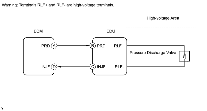
The problem area can be identified by checking the waveform at the following terminals.
Tech Tips
A and D are on the ECM side, and B and C are on the EDU side.
| Malfunction Point | Trouble Area |
|---|---|
| A |
|
| B (If A is normal) |
|
| C (If A and B are normal) |
|
| D (If A, B and C are normal) |
|
MONITOR STRATEGY
| Required sensor | EDU |
| Frequency of operation | Continuous |
| Duration | 3 seconds |
| MIL operation | 1 driving cycle |
| Required sensors | Fuel pressure sensor |
| Frequency of operation | Once per driving cycle |
| Duration | 1 second |
| MIL operation | 2 driving cycles |
TYPICAL ENABLING CONDITIONS
| Specification |
|---|
| Drive the vehicle at 50 km/h (31 mph) in 3rd gear and then decelerate by completely releasing the accelerator pedal |
| Item | Specification | |
|---|---|---|
| Minimum | Maximum | |
| Fuel pressure | 27000 kPa (275 kgf/cm2, 3915 psi) |
- |
| Fuel temperature | 0°C (32°F) | - |
| Battery voltage | 11 V | - |
| The monitor will not run if the fuel pressure sensor, pressure discharge valve circuit, or fuel temperature sensor is malfunctioning | ||
TYPICAL MALFUNCTION THRESHOLDS
| Specification |
|---|
| There are no confirmation signals from the EDU, despite the ECM sending the command signals regularly during deceleration |
| Specification |
|---|
| The internal pressure stays beyond the specified level after the ignition switch was turned OFF |
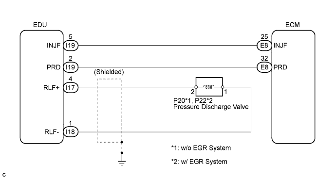
WIRING DIAGRAM
INSPECTION PROCEDURE
Note
After replacing the ECM, the new ECM needs registration Click here and initialization Click here.
Tech Tips
-
After completing repairs, confirm that P1271 and/or P1272 does not recur.
-
If P0200 and P1271 are present simultaneously, there is an open circuit in the INJF wire harness between the EDU and ECM, or in the wire harness for both injector and pressure discharge valve.
-
Read freeze frame data using the intelligent tester. Freeze frame data records the engine condition when malfunctions are detected. When troubleshooting, freeze frame data can help determine if the vehicle was moving or stationary, if the engine was warmed up or not, and other data from the time the malfunction occurred.
PROCEDURE
-
READ DTC OUTPUT (DTC P1271 AND/OR P1272)
-
Connect the intelligent tester to the DLC3.
-
Turn the ignition switch ON and turn the tester ON.
-
Enter the following menus: Powertrain / Engine and ECT / DTC.
-
Read DTCs.
Result Display (DTC output) Proceed to P1271 and/or P1272 A P1272 B
B 
REPLACE COMMON RAIL ASSEMBLY (PRESSURE DISCHARGE VALVE) Click here
A 
-
-
INSPECT COMMON RAIL ASSEMBLY (PRESSURE DISCHARGE VALVE)
-
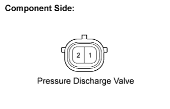
Disconnect the pressure discharge valve connector.
-
Measure the resistance of the pressure discharge valve.
Standard resistance Tester Connection Condition Specified Condition 1 - 2 20°C (68°F) 0.85 to 1.05 Ω
NG 
REPLACE COMMON RAIL ASSEMBLY Click here
OK
-
-
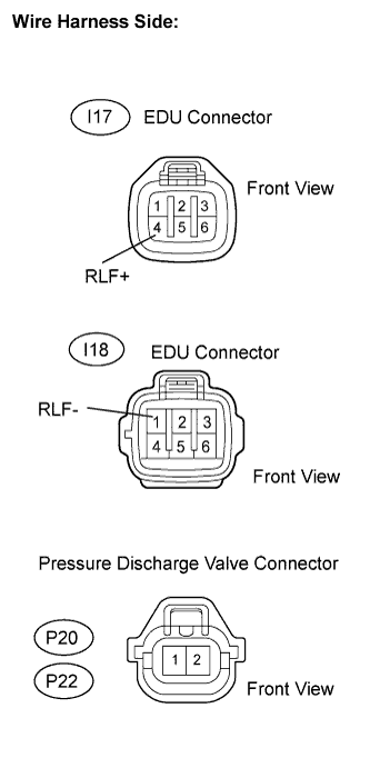
CHECK HARNESS AND CONNECTOR (PRESSURE DISCHARGE VALVE - EDU)
-
w/o EGR System
-
Disconnect the I17 and I18 EDU connectors.
-
Disconnect the P20 pressure discharge valve connector.
-
Measure the resistance of the wire harness side connectors.
Standard resistance Tester Connection Specified Condition RLF+ (I17-4) - P20-2 Below 1 Ω RLF- (I18-1) - P20-1 Below 1 Ω RLF+ (I17-4) or P20-2 - Body ground 10 kΩ or higher RLF- (I18-1) or P20-1 - Body ground 10 kΩ or higher
-
-
w/ EGR System
-
Disconnect the I17 and I18 EDU connectors.
-
Disconnect the P22 pressure discharge valve connector.
-
Measure the resistance of the wire harness side connectors.
Standard resistance Tester Connection Specified Condition RLF+ (I17-4) - P22-2 Below 1 Ω RLF- (I18-1) - P22-1 Below 1 Ω RLF+ (I17-4) or P22-2 - Body ground 10 kΩ or higher RLF- (I18-1) or P22-1 - Body ground 10 kΩ or higher
-
NG
REPAIR OR REPLACE HARNESS OR CONNECTOR
OK
-
-
CHECK HARNESS AND CONNECTOR (ECM - EDU)
-
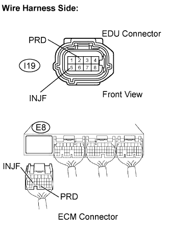
Disconnect the I19 EDU connectors.
-
Disconnect the E8 ECM connector.
-
Measure the resistance of the wire harness side connectors.
Standard resistance Tester Connection Specified Condition PRD (E8-32) - PRD (I19-2) Below 1 Ω INJF (E8-25) - INJF (I19-5) Below 1 Ω PRD (E8-32) or PRD (I19-2) - Body ground 10 kΩ or higher INJF (E8-25) or INJF (I19-5) - Body ground 10 kΩ or higher
NG
REPAIR OR REPLACE HARNESS OR CONNECTOR
OK
-
-
INSPECT INJECTOR DRIVER (BATTERY VOLTAGE)
-
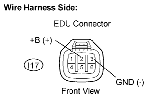
Disconnect the I17 EDU connector.
-
Turn the ignition switch ON.
-
Measure the voltage of the EDU connector.
Standard voltage Tester Connection Specified Condition +B (I17-2) - GND (I17-3) 11 to 14 V
NG
CHECK INJECTOR DRIVER POWER SOURCE CIRCUIT (EDU - BATTERY)
OK
-
-
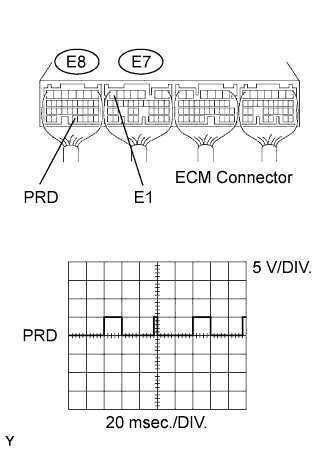
INSPECT ECM (PRD VOLTAGE)
-
Inspect the ECM using the oscilloscope.
-
Drive the vehicle at 50 km/h (31 mph) in the third gear, and then decelerate by releasing the accelerator pedal.
-
Check the waveform between the terminal of the E7 and E8 ECM connectors.
Standard Tester Connection Specified Condition PRD (E8-32) - E1 (E7-7) Correct waveform shown Tech Tips
Alternative inspection:
Run the engine at 2500 rpm for 10 seconds and then decrease the engine speed to idling by completely releasing the accelerator pedal.
NG
REPLACE ECM Click here
OK
-
-
REPLACE INJECTOR DRIVER
-
Replace the injector driver Click here.
NEXT
-
-
CHECK IF DTC OUTPUT RECURS (DTC P1271 AND/OR P1272)
Tech Tips
P1271:
After clearing the DTC, drive the vehicle at 50 km/h (31 mph) in the third gear and then decelerate by releasing the accelerator pedal. Confirm that DTC P1271 is not present again.
P1272:
After clearing the DTC, start and stop the engine twice, and then confirm that DTC P1272 is not present again.
NEXT 
END
-
REPLACE COMMON RAIL ASSEMBLY (PRESSURE DISCHARGE VALVE)
-
Replace common rail assembly Click here.
NEXT
-
-
CHECK IF DTC OUTPUT RECURS (DTC P1271 AND/OR P1272)
Tech Tips
P1271:
After clearing the DTC, drive the vehicle at 50 km/h (31 mph) in the third gear and then decelerate by releasing the accelerator pedal. Confirm that DTC P1271 is not present again.
P1272:
After clearing the DTC, start and stop the engine twice, and then confirm that DTC P1272 is not present again.
NEXT
END