SUB BATTERY RELAY REMOVAL
CAUTION / NOTICE / HINT
The necessary procedures (adjustment, calibration, initialization or registration) that must be performed after parts are removed and installed, or replaced during the backup relay removal/installation are shown below.
| Replacement Part or Procedure | Necessary Procedure | Effect/Inoperative when not Performed | Link |
|---|---|---|---|
| Disconnect cable from negative battery terminal | Drive the vehicle until stop and start control is permitted (approximately 5 to 60 minutes) | Stop and start system | |
| Memorize steering angle neutral point | LKA /LDA system | ||
| Parking support brake system* | |||
| Pre-collision system | |||
| Adaptive high beam system | |||
Lighting system (EXT) |
|||
| Variable gear ratio steering system | |||
| Parking assist monitor system | |||
| Panoramic view monitor system | |||
| Initialize rear door sunshade system | Rear door sunshade system | ||
| Initialize power trunk lid system | Power trunk lid system |
Click here Click here
Note
After the engine switch is turned off, the navigation system requires approximately a minute to record various types of memory and settings. As a result, after turning the engine switch off, wait a minute or more before disconnecting the cable from the negative (-) battery terminal.
PROCEDURE
-
REMOVE REAR COOLING UNIT ASSEMBLY (w/ Rear Cooler)
-
REMOVE LUGGAGE COMPARTMENT MAT SUB-ASSEMBLY
-
REMOVE TOOL BOX
-
PRECAUTION
Note
After turning the engine switch off, waiting time may be required before disconnecting the cable from the negative (-) battery terminal. Therefore, make sure to read the disconnecting the cable from the negative (-) battery terminal notices before proceeding with work.
-
DISCONNECT CABLE FROM NEGATIVE BATTERY TERMINAL
Note
When disconnecting the cable, some systems need to be initialized after the cable is reconnected.
-
REMOVE BATTERY
-
REMOVE LUGGAGE COMPARTMENT FLOOR MAT
-
REMOVE LUGGAGE COMPARTMENT TRIM COVER LH
-
REMOVE LUGGAGE COMPARTMENT TRIM COVER RH
-
REMOVE SIDE TRIM BOX
-
REMOVE LUGGAGE COMPARTMENT TRIM BOX (w/o Air Suspension)
-
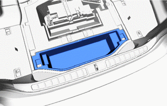
Remove the luggage compartment trim box.
-
-
REMOVE ROPE HOOK ASSEMBLY
-
REMOVE REAR FLOOR FINISH PLATE
-
REMOVE INNER LOWER LUGGAGE COMPARTMENT TRIM COVER
-
REMOVE NO. 1 LUGGAGE COMPARTMENT LIGHT ASSEMBLY
-
REMOVE FRONT LUGGAGE COMPARTMENT TRIM COVER
-
REMOVE REAR LUGGAGE COMPARTMENT TRIM COVER
-
REMOVE LUGGAGE COMPARTMENT TRIM COVER ASSEMBLY RH
-
REMOVE LUGGAGE COMPARTMENT TRIM COVER ASSEMBLY LH
-
REMOVE REAR LUGGAGE COMPARTMENT TRAY BRACKET RH
-
REMOVE BATTERY CARRIER CATCH BRACKET SUB-ASSEMBLY
-
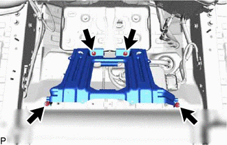
Remove the 4 nuts and the battery carrier catch bracket sub-assembly.
-
-
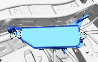
REMOVE BATTERY CARRIER ASSEMBLY
-
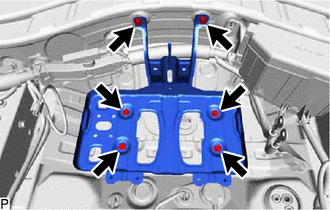
Remove the 6 bolts and battery carrier assembly.
-
-
REMOVE CONNECTOR COVER
-
REMOVE LUGGAGE ROOM RELAY BLOCK
-
Loosen the nut and disconnect the positive (+) terminal of the sub-battery from the sub-battery module assembly.
-
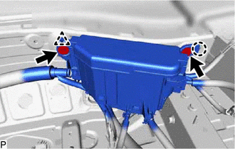
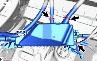
Remove the 2 bolts from the luggage room relay block.
-
Detach the clamp and claw and disconnect the luggage room relay block.
-
Remove the relay block cover.
-
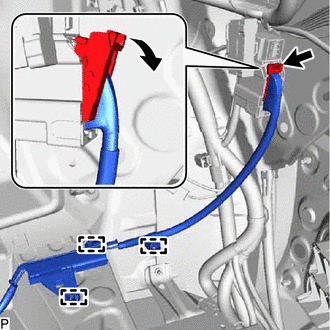
Lift up the lock lever and disconnect the connector as shown in the illustration.
-
Detach the 3 clamps and disconnect the luggage room relay block harness from the luggage room panel.
-
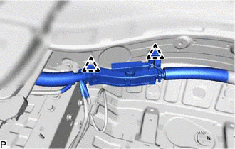
Detach the 2 clamps and disconnect the luggage room relay block harness from the luggage room panel.
-
w/ Dynamic Rear Steering:
-
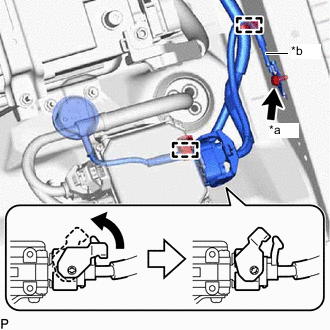
*a Ground Wire Bolt *b Ground Wire Lift up the lock lever and disconnect the connector of the DRS control ECU as shown in the illustration.
-
Remove the bolt and ground wire.
-
Detach the 2 clamps and disconnect the luggage room relay block harness from the luggage room panel.
-
-
-
REMOVE BACKUP RELAY
-
*a Luggage Room Relay Block Lower Side Detach the clamp and disconnect the 3 tie wraps from the luggage room relay block.
-
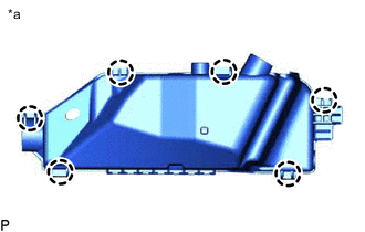
*a Luggage Room Relay Block Lower Side Detach the 6 claws and remove the relay block lower cover from the luggage room relay block.
-
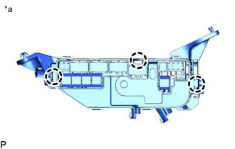
*a Luggage Room Relay Block Upper Side Detach the 3 claws and disconnect the relay block assembly from the luggage room relay block.
-
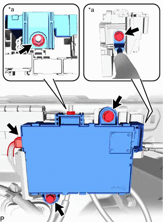
*a Backup Relay Terminal Side Loosen the bolt and nut and remove them from the backup relay terminal.
-
Loosen the 2 bolts and remove them from the backup relay.
-
Disconnect the connector from the backup relay.
-
Detach the claw and remove the backup relay from the relay block assembly.
-