AUDIO AND VISUAL SYSTEM(for 8 Inch Display), Diagnostic DTC:B1324, B1325
| DTC Code | DTC Name |
|---|---|
| B1324 | Lost Communication with Meter |
| B1325 | Lost Communication with HUD |
DESCRIPTION
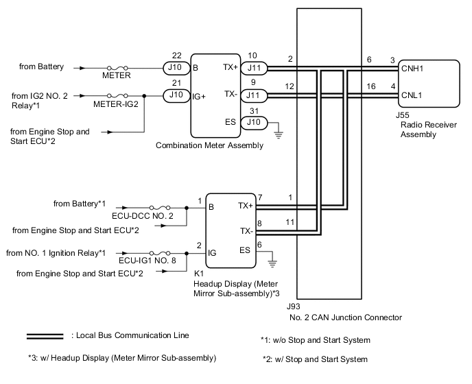
These DTCs are stored when communication between the radio receiver assembly and combination meter assembly or headup display (meter mirror sub-assembly)*1 is not possible.
| DTC No. | Detection Item | DTC Detection Condition | Trouble Area |
|---|---|---|---|
| B1324 | Lost Communication with Meter | After the radio receiver assembly receives a registration information signal, which is sent by the combination meter assembly when the engine switch is on (ACC), 1 or more times, the radio receiver assembly does not receive the signal for 30 seconds or more. |
|
| B1325 | Lost Communication with HUD | After the radio receiver assembly receives a registration information signal, which is sent by the headup display (meter mirror sub-assembly) when the engine switch is on (ACC), 1 or more times, the radio receiver assembly does not receive the signal for 30 seconds or more.*1 |
|
-
*1: w/ Headup Display (Meter Mirror Sub-assembly)
-
*2: w/ Stop and Start System
Tech Tips
The radio receiver assembly is the master unit.
WIRING DIAGRAM
CAUTION / NOTICE / HINT
Note
-
Inspect the fuses for circuits related to this system before performing the following procedure.
-
After turning the engine switch off, waiting time may be required before disconnecting the cable from the negative (-) battery terminal. Therefore, make sure to read the disconnecting the cable from the negative (-) battery terminal notices before proceeding with work.
PROCEDURE
-
CHECK DTC
-
Clear the DTCs.
Body Electrical > Navigation System > Clear DTCs -
Recheck for DTCs and check that no DTCs are output.
Body Electrical > Navigation System > Trouble CodesResult Result Proceed to All DTCs are not output A DTCs B1324 and B1325 are output
(w/ Headup Display (Meter Mirror Sub-assembly))
B DTC B1324 is output C DTC B1325 is output
(w/ Headup Display (Meter Mirror Sub-assembly))
D
A 
USE SIMULATION METHOD TO CHECK Click here
C 
CHECK HARNESS AND CONNECTOR (COMBINATION METER ASSEMBLY POWER SOURCE) Click here
D
CHECK HARNESS AND CONNECTOR (HEADUP DISPLAY (METER MIRROR SUB-ASSEMBLY) POWER SOURCE) Click here
B 
-
-
CHECK LOCAL BUS
-
Disconnect the cable from the negative (-) battery terminal.
-
Measure the resistance according to the value(s) in the table below.
Standard Resistance Tester Connection Condition Specified Condition J93-6 - J93-16 Cable disconnected from negative (-) battery terminal 54 to 69 Ω Result Result Proceed to OK A NG (Below 54 Ω) B NG (70 Ω or higher) C
A
USE SIMULATION METHOD TO CHECK Click here
C
CHECK HARNESS AND CONNECTOR (RADIO RECEIVER ASSEMBLY - NO. 2 CAN JUNCTION CONNECTOR) Click here
B
-
-
CHECK HARNESS AND CONNECTOR (RADIO RECEIVER ASSEMBLY - NO. 2 CAN JUNCTION CONNECTOR)
-
Disconnect the cable from the negative (-) battery terminal.
-
Disconnect the J93 No. 2 CAN junction connector.
-
Connect the J55 radio receiver assembly connector.
-
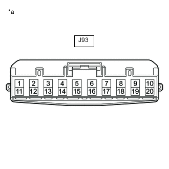
*a Front view of wire harness connector
(to No. 2 CAN Junction Connector)
Measure the resistance according to the value(s) in the table below.
Standard Resistance Tester Connection Condition Specified Condition J93-6 - J93-16 Cable disconnected from negative (-) battery terminal 108 to 132 Ω Result Proceed to OK NG
NG
CHECK HARNESS AND CONNECTOR (RADIO RECEIVER ASSEMBLY - NO. 2 CAN JUNCTION CONNECTOR) Click here
OK
-
-
CHECK HARNESS AND CONNECTOR (COMBINATION METER ASSEMBLY - NO. 2 CAN JUNCTION CONNECTOR)
-
Disconnect the cable from the negative (-) battery terminal.
-
Disconnect the J93 No. 2 CAN junction connector.
-
Connect the J11 combination meter assembly connector.
-
*a Front view of wire harness connector
(to No. 2 CAN Junction Connector)
Measure the resistance according to the value(s) in the table below.
Standard Resistance Tester Connection Condition Specified Condition J93-2 - J93-12 Cable disconnected from negative (-) battery terminal 108 to 132 Ω Result Result Proceed to OK (w/o Headup Display (Meter Mirror Sub-assembly)) A OK (w/ Headup Display (Meter Mirror Sub-assembly)) B NG C
A
REPLACE NO. 2 CAN JUNCTION CONNECTOR
C
CHECK HARNESS AND CONNECTOR (COMBINATION METER ASSEMBLY - NO. 2 CAN JUNCTION CONNECTOR) Click here
B
-
-
CHECK HARNESS AND CONNECTOR (HEADUP DISPLAY (METER MIRROR SUB-ASSEMBLY) - NO. 2 CAN JUNCTION CONNECTOR)
-
Disconnect the cable from the negative (-) battery terminal.
-
Disconnect the J93 No. 2 CAN junction connector.
-
Connect the K1 headup display (meter mirror sub-assembly) connector.
-
*a Front view of wire harness connector
(to No. 2 CAN Junction Connector)
Measure the resistance according to the value(s) in the table below.
Standard Resistance Tester Connection Condition Specified Condition J93-1 - J93-11 Cable disconnected from negative (-) battery terminal 200 Ω or higher Result Proceed to OK NG
OK
REPLACE NO. 2 CAN JUNCTION CONNECTOR
NG
-
-
CHECK HARNESS AND CONNECTOR (HEADUP DISPLAY (METER MIRROR SUB-ASSEMBLY) - NO. 2 CAN JUNCTION CONNECTOR)
-
Disconnect the cable from the negative (-) battery terminal.
-
Disconnect the K1 headup display (meter mirror sub-assembly) connector.
-
Connect the J93 No. 2 CAN junction connector.
-
Measure the resistance according to the value(s) in the table below.
Standard Resistance Tester Connection Condition Specified Condition K1-7 (TX+) - K1-8 (TX-) Cable disconnected from negative (-) battery terminal 54 to 69 Ω Result Proceed to OK NG
OK
REPLACE HEADUP DISPLAY (METER MIRROR SUB-ASSEMBLY) Click here
NG
REPAIR OR REPLACE HARNESS OR CONNECTOR
-
-
CHECK HARNESS AND CONNECTOR (COMBINATION METER ASSEMBLY - NO. 2 CAN JUNCTION CONNECTOR)
-
Disconnect the cable from the negative (-) battery terminal.
-
Disconnect the J11 combination meter assembly connector.
-
Connect the J93 No. 2 CAN junction connector.
-
*a Front view of wire harness connector
(to No. 2 CAN Junction Connector)
Measure the resistance according to the value(s) in the table below.
Standard Resistance Tester Connection Condition Specified Condition J93-2 - J93-12 Cable disconnected from negative (-) battery terminal 108 to 132 Ω Result Proceed to OK NG
OK
REPLACE COMBINATION METER ASSEMBLY Click here
NG
REPAIR OR REPLACE HARNESS OR CONNECTOR
-
-
CHECK HARNESS AND CONNECTOR (RADIO RECEIVER ASSEMBLY - NO. 2 CAN JUNCTION CONNECTOR)
-
Disconnect the cable from the negative (-) battery terminal.
-
Disconnect the J55 radio receiver assembly connector.
-
Connect the J93 No. 2 CAN junction connector.
-
*a Front view of wire harness connector
(to No. 2 CAN Junction Connector)
Measure the resistance according to the value(s) in the table below.
Standard Resistance Tester Connection Condition Specified Condition J93-6 - J93-16 Cable disconnected from negative (-) battery terminal 108 to 132 Ω Result Proceed to OK NG
OK
REPLACE RADIO RECEIVER ASSEMBLY Click here
NG
REPAIR OR REPLACE HARNESS OR CONNECTOR
-
-
CHECK HARNESS AND CONNECTOR (RADIO RECEIVER ASSEMBLY - NO. 2 CAN JUNCTION CONNECTOR)
-
Disconnect the cable from the negative (-) battery terminal.
-
Disconnect the J55 radio receiver assembly connector.
-
Connect the J93 No. 2 CAN junction connector.
-
Measure the resistance according to the value(s) in the table below.
Standard Resistance Tester Connection Condition Specified Condition J55-3 (CNH1) - J55-4 (CNL1) Cable disconnected from negative (-) battery terminal 108 to 132 Ω Result Proceed to OK NG
OK
REPLACE RADIO RECEIVER ASSEMBLY Click here
NG
-
-
CHECK HARNESS AND CONNECTOR (RADIO RECEIVER ASSEMBLY - NO. 2 CAN JUNCTION CONNECTOR)
-
Disconnect the cable from the negative (-) battery terminal.
-
Disconnect the J93 No. 2 CAN junction connector.
-
Connect the J55 radio receiver assembly connector.
-
*a Front view of wire harness connector
(to No. 2 CAN Junction Connector)
Measure the resistance according to the value(s) in the table below.
Standard Resistance Tester Connection Condition Specified Condition J93-6 - J93-16 Cable disconnected from negative (-) battery terminal 108 to 132 Ω Result Proceed to OK NG
OK
REPLACE NO. 2 CAN JUNCTION CONNECTOR
NG
REPAIR OR REPLACE HARNESS OR CONNECTOR
-
-
CHECK HARNESS AND CONNECTOR (COMBINATION METER ASSEMBLY POWER SOURCE)
-
Disconnect the J10 combination meter assembly connector.
-
Measure the resistance according to the value(s) in the table below.
Standard Resistance Tester Connection Condition Specified Condition J10-31 (ES) - Body ground Always Below 1 Ω -
Measure the voltage according to the value(s) in the table below.
Standard Voltage Tester Connection Condition Specified Condition J10-22 (B) - Body ground Always 11 to 14 V J10-21 (IG+) - Body ground Engine switch on (IG) 11 to 14 V*1
9.5 to 14 V*2
-
*1: w/o Stop and Start System
*2: w/ Stop and Start System
Result Result Proceed to OK A NG (w/o Stop and Start System) B NG (w/ Stop and Start System) C -
B
REPAIR OR REPLACE HARNESS OR CONNECTOR
C
GO TO STOP AND START SYSTEM Click here
A
-
-
CHECK HARNESS AND CONNECTOR (COMBINATION METER ASSEMBLY - NO. 2 CAN JUNCTION CONNECTOR)
-
Disconnect the cable from the negative (-) battery terminal.
-
Disconnect the J11 combination meter assembly connector.
-
Measure the resistance according to the value(s) in the table below.
Standard Resistance Tester Connection Condition Specified Condition J11-10 (TX+) - J11-9 (TX-) Cable disconnected from negative (-) battery terminal 108 to 132 Ω Result Proceed to OK NG
OK
REPLACE COMBINATION METER ASSEMBLY Click here
NG
REPAIR OR REPLACE HARNESS OR CONNECTOR
-
-
CHECK HARNESS AND CONNECTOR (HEADUP DISPLAY (METER MIRROR SUB-ASSEMBLY) POWER SOURCE)
-
Disconnect the K1 headup display (meter mirror sub-assembly) connector.
-
Measure the resistance according to the value(s) in the table below.
Standard Resistance Tester Connection Condition Specified Condition K1-6 (ES) - Body ground Always Below 1 Ω -
Measure the voltage according to the value(s) in the table below.
Standard Voltage Tester Connection Condition Specified Condition K1-1 (B) - Body ground Always 11 to 14 V*1
9.5 to 14 V*2
K1-2 (IG) - Body ground Engine switch on (IG) 11 to 14 V*1
9.5 to 14 V*2
-
*1: w/o Stop and Start System
*2: w/ Stop and Start System
Result Result Proceed to OK A NG (w/o Stop and Start System) B NG (w/ Stop and Start System) C -
B
REPAIR OR REPLACE HARNESS OR CONNECTOR
C
GO TO STOP AND START SYSTEM Click here
A
-
-
CHECK HARNESS AND CONNECTOR (HEADUP DISPLAY (METER MIRROR SUB-ASSEMBLY) - NO. 2 CAN JUNCTION CONNECTOR)
-
Disconnect the cable from the negative (-) battery terminal.
-
Disconnect the K1 headup display (meter mirror sub-assembly) connector.
-
Measure the resistance according to the value(s) in the table below.
Standard Resistance Tester Connection Condition Specified Condition K1-7 (TX+) - K1-8 (TX-) Cable disconnected from negative (-) battery terminal 54 to 69 Ω Result Proceed to OK NG
OK
REPLACE HEADUP DISPLAY (METER MIRROR SUB-ASSEMBLY) Click here
NG
REPAIR OR REPLACE HARNESS OR CONNECTOR
-