CAMSHAFT REMOVAL

CAUTION / NOTICE / HINT
The necessary procedures (adjustment, calibration, initialization, or registration) that must be performed after parts are removed, installed, or replaced during the camshaft removal/installation are shown below.
| Replaced Part or Performed Procedure | Necessary Procedure | Effect/Inoperative Function when Necessary Procedure not Performed | Link |
|---|---|---|---|
| Battery terminal is disconnected/reconnected | Drive the vehicle until stop and start control is permitted (approximately 5 to 60 minutes) | Stop and start system | |
| Memorize steering angle neutral point | LKA/LDA system | ||
| Parking support brake system* | |||
| Pre-collision system | |||
| Adaptive high beam system | |||
Lighting system (EXT) |
|||
| Variable gear ratio steering system | |||
| Parking assist monitor system | |||
| Panoramic view monitor system | |||
| Initialize rear door sunshade system | Rear door sunshade system | ||
| Initialize power trunk lid system | Power trunk lid system | ||
|
Inspection after repairs |
|
w/ Canister Pump Module: w/o Canister Pump Module: |
Click here Click here
Note
This procedure includes the removal of small-head bolts. Refer to Small-Head Bolts of Basic Repair Hint to identify the small-head bolts.
PROCEDURE
-
DRAIN ENGINE COOLANT
-
PRECAUTION
Note
After turning the engine switch off, waiting time may be required before disconnecting the cable from the battery terminal. Therefore, make sure to read the disconnecting the cable from the battery terminal notice before proceeding with work.
-
REMOVE LUGGAGE COMPARTMENT MAT SUB-ASSEMBLY
-
REMOVE TOOL BOX
-
DISCONNECT CABLE FROM NEGATIVE BATTERY TERMINAL
Note
When disconnecting the cable, some systems need to be initialized after the cable is reconnected.
-
REMOVE CRANKSHAFT DAMPER SUB-ASSEMBLY
-
REMOVE VACUUM PUMP ASSEMBLY
-
REMOVE TIMING CHAIN COVER PLATE
-
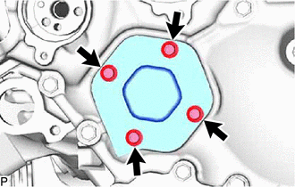
Remove the 4 bolts, timing chain cover plate.
-

Remove the gasket.
-
-
SET NO. 1 CYLINDER TO TDC/COMPRESSION
-
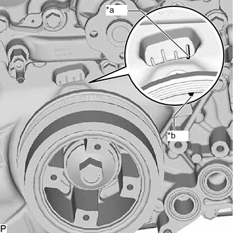
*a "0" Timing Mark *b Timing Mark (Cutout) Turn the crankshaft clockwise to align the timing mark (cutout) on the crankshaft pulley assembly with the "0" timing mark on the timing chain cover assembly.
-

*A for Bank 2 *B for Bank 1 *a Paint Mark *b Timing Mark Place paint marks on the timing marks and sprockets of each camshaft timing gear and on the links of the chain.
Tech Tips
Attach paint marks to the 2 chain links at the position where the timing mark of the camshaft timing gear is located and at the opposite position of the timing chain or belt cover sub-assembly.
-
-
REMOVE NO. 1 CHAIN TENSIONER ASSEMBLY (for Bank 1)
-

Turn the crankshaft approximately 30° counterclockwise so that there is some slack in the chain.
Tech Tips
This prevents the valves and pistons from interfering with each other.
-

*a Lever Hole *b Tensioner Hole *c Pin Align the hole in the lever of the No. 1 chain tensioner assembly with the hole in the tensioner body as shown in the illustration, and then insert a pin with a diameter of 1.27 mm (0.0500 in.) into the hole.
-
*a "0" Timing Mark *b Timing Mark (Cutout) Turn the crankshaft clockwise to align the timing mark (cutout) on the crankshaft pulley assembly with the "0" timing mark on the timing chain cover assembly.
-
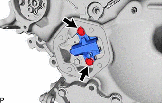
Remove the 2 bolts and No. 1 chain tensioner assembly.
Note
Do not drop the No. 1 chain tensioner assembly or bolts into the timing chain cover assembly.
-
-
DISCONNECT NO. 1 CHAIN SUB-ASSEMBLY (for Bank 1)
-

Turn the crankshaft clockwise until it is in the position shown in the illustration so that there is some slack in the No. 1 chain sub-assembly between the banks.
CAUTION:
As the camshafts turn suddenly, do not touch the camshafts or camshaft timing gears.
Tech Tips
When turning the crankshaft, engine oil may spray out of the oil holes.
-

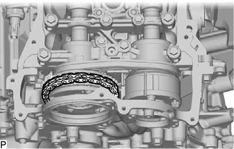
*a 95° to 100° Turn the crankshaft clockwise until it is in the position shown in the illustration so that the chain can be removed easily.
Note
When turning the crankshaft, engine oil may spray out of the oil holes.
-

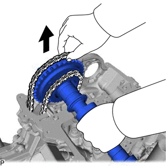
Remove the No. 1 chain sub-assembly from the sprocket of the camshaft timing gear and set it on the gear.
CAUTION:
As the camshaft may turn suddenly and pinch your fingers when the No. 1 chain sub-assembly is removed, pinch the No. 1 chain sub-assembly and lift it upward to remove it from the sprocket.
-
-
REMOVE CAMSHAFT BEARING CAP (for Bank 1)
-
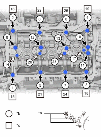
*a Replacement Bolt and Washer *b Part Removal *c Replacement Bolt and Washer Installation Remove the bolts and bearing caps in the order shown in the illustration. Immediately after removing a bearing cap, install replacement bolts and washers in the order shown in the illustration.
- Torque:
- 10 N*m { 102 kgf*cm, 7 ft.*lbf }
Note
-
Do not install the bearing caps when installing replacement bolts and washers.
-
Be sure to follow the numerical order when performing this procedure.
-
Do not allow replacement bolts or washers to contact the camshaft.
-
Do not drop replacement bolts or washers into the cylinder head sub-assembly.
Tech Tips
-
Arrange the removed parts so that they can be reinstalled in their original locations.
-
Part number for replacement bolts: 91551-F0840 (8 bolts)
-
Part number for replacement washers: 90201-12028 (16 washers)
-

*1 No. 2 Chain Tensioner Assembly *a No. 2 Chain Tensioner Assembly Chain Plunger While one person lifts up the intake camshaft sub-assembly RH and exhaust camshaft sub-assembly RH, have another person remove the No. 1 camshaft bearing cap.
Note
Remove the No. 1 camshaft bearing cap while holding down the chain plunger of the No. 2 chain tensioner assembly.
-
-
REMOVE EXHAUST CAMSHAFT SUB-ASSEMBLY RH
-

Lift up the rear of the exhaust camshaft sub-assembly RH so that it is at an angle.
-
With the No. 2 chain sub-assembly raised, pass it out through the exhaust camshaft sub-assembly LH towards the front of the vehicle to remove it.
-
-
REMOVE CAMSHAFT TIMING EXHAUST GEAR ASSEMBLY RH (for Bank 1)
-

*a Hexagonal Portion Using SST, grip the hexagonal portion, and then secure SST and exhaust camshaft sub-assembly RH in a vise as shown in the illustration.
- SST
- 09212-31010
Note
-
Do not damage the exhaust camshaft sub-assembly RH.
-
Never grip areas other than the hexagonal portion, as this may cause damage.
-

Using a 5 mm hexagon socket wrench, remove the bolt.
-
Remove the camshaft timing oil control valve assembly (exhaust camshaft timing gear bolt assembly) from the camshaft timing exhaust gear assembly.
-

Using a 5 mm hexagon socket wrench, remove the 2 bolts and camshaft timing exhaust gear assembly from the exhaust camshaft sub-assembly RH.
Note
-
Be careful not to damage the exhaust camshaft sub-assembly RH and camshaft timing exhaust gear assembly.
-
Do not disassemble the camshaft timing exhaust gear assembly.
-
-
-
REMOVE INTAKE CAMSHAFT SUB-ASSEMBLY RH
-

Remove the No. 2 chain sub-assembly from the sprocket of the camshaft timing gear and set it on the gear.
-
Lift up the rear end of the camshaft so that it is tilted to remove the No. 1 chain sub-assembly.
-
Remove the intake camshaft sub-assembly RH.
-
-
REMOVE CAMSHAFT TIMING INTAKE GEAR ASSEMBLY RH (for Bank 1)
-

*a Hexagonal Portion Using SST, grip the hexagonal portion, and then secure SST and intake camshaft sub-assembly RH in a vise as shown in the illustration.
- SST
- 09212-31010
Note
-
Do not damage the intake camshaft sub-assembly RH.
-
Never grip areas other than the hexagonal portion, as this may cause damage.
-

Using a 10 mm bi-hexagonal wrench, remove the bolt and camshaft timing intake gear assembly RH from the intake camshaft sub-assembly RH.
Note
-
Be careful not to damage the intake camshaft sub-assembly RH and camshaft timing intake gear assembly RH.
-
Do not disassemble the camshaft timing intake gear assembly RH.
-
-
-
SET NO. 1 CYLINDER TO TDC/COMPRESSION
-
REMOVE NO. 1 CHAIN TENSIONER ASSEMBLY (for Bank 2)
-
DISCONNECT NO. 1 CHAIN SUB-ASSEMBLY (for Bank 2)
-
Turn the crankshaft clockwise until it is in the position shown in the illustration so that there is some slack in the No. 1 chain sub-assembly between the banks.
CAUTION:
As the camshafts turn suddenly, do not touch the camshafts or camshaft timing gears.
Tech Tips
When turning the crankshaft, engine oil may spray out of the oil holes.
-
*a 95° to 100° Turn the crankshaft clockwise until it is in the position shown in the illustration so that the chain can be removed easily.
Note
When turning the crankshaft, engine oil may spray out of the oil holes.
-
Remove the No. 1 chain sub-assembly from the sprocket of the camshaft timing gear and set it on the gear.
CAUTION:
As the camshaft may turn suddenly and pinch your fingers when the No. 1 chain sub-assembly is removed, pinch the No. 1 chain sub-assembly and lift it upward to remove it from the sprocket.
-
-
REMOVE CAMSHAFT BEARING CAP (for Bank 2)
-

*a Replacement Bolt and Washer *b Part Removal *c Replacement Bolt and Washer Installation Remove the bolts and bearing caps in the order shown in the illustration. Immediately after removing a bearing cap, install replacement bolts and washers in the order shown in the illustration.
- Torque:
- 10 N*m { 102 kgf*cm, 7 ft.*lbf }
Note
-
Do not install the bearing caps when installing replacement bolts and washers.
-
Be sure to follow the numerical order when performing this procedure.
-
Do not allow replacement bolts or washers to contact the camshaft.
-
Do not drop replacement bolts or washers into the cylinder head sub-assembly.
Tech Tips
-
Arrange the removed parts so that they can be reinstalled in their original locations.
-
Part number for replacement bolts: 91551-F0840 (8 bolts)
-
Part number for replacement washers: 90201-12028 (16 washers)
-
-
REMOVE EXHAUST CAMSHAFT SUB-ASSEMBLY LH
-

Lift up the rear of the exhaust camshaft sub-assembly LH so that it is at an angle.
-
With the No. 2 chain sub-assembly raised, pass it out through the exhaust camshaft sub-assembly LH towards the front of the vehicle to remove it.
-
-
REMOVE CAMSHAFT TIMING EXHAUST GEAR ASSEMBLY LH (for Bank 2)
-
*a Hexagonal Portion Using SST, grip the hexagonal portion, and then secure SST and exhaust camshaft sub-assembly LH in a vise as shown in the illustration.
- SST
- 09212-31010
Note
-
Do not damage the exhaust camshaft sub-assembly LH.
-
Never grip areas other than the hexagonal portion, as this may cause damage.
-
Using a 5 mm hexagon socket wrench, remove the bolt.
-
Remove the camshaft timing oil control valve assembly (exhaust camshaft timing gear bolt assembly) from the camshaft timing exhaust gear assembly.
-
Using a 5 mm hexagon socket wrench, remove the 2 bolts and camshaft timing exhaust gear assembly from the exhaust camshaft sub-assembly LH.
Note
-
Be careful not to damage the exhaust camshaft sub-assembly LH and camshaft timing exhaust gear assembly LH.
-
Do not disassemble the camshaft timing exhaust gear assembly LH.
-
-
-
REMOVE INTAKE CAMSHAFT SUB-ASSEMBLY LH
-
Remove the No. 2 chain sub-assembly from the sprocket of the camshaft timing gear and set it on the gear.
-

Lift up the rear end of the camshaft so that it is tilted to remove the No. 1 chain sub-assembly.
-
Remove the intake camshaft sub-assembly LH.
-
-
REMOVE CAMSHAFT TIMING INTAKE GEAR ASSEMBLY LH (for Bank 2)
-
*a Hexagonal Portion Using SST, grip the hexagonal portion, and then secure SST and intake camshaft sub-assembly LH in a vise as shown in the illustration.
- SST
- 09212-31010
Note
-
Do not damage the intake camshaft sub-assembly LH.
-
Never grip areas other than the hexagonal portion, as this may cause damage.
-
Using a 10 mm bi-hexagonal wrench, remove the bolt and camshaft timing intake gear assembly LH from the intake camshaft sub-assembly LH.
Note
-
Be careful not to damage the intake camshaft sub-assembly LH and camshaft timing intake gear assembly LH.
-
Do not disassemble the camshaft timing intake gear assembly LH.
-
-