BRAKE BOOSTER(for RHD) INSTALLATION
PROCEDURE
-
INSTALL BRAKE BOOSTER GASKET
-
Install a new brake booster gasket to the brake booster assembly.
-
-
INSTALL BRAKE BOOSTER ASSEMBLY
-
Temporarily install the brake booster assembly to the vehicle body.
Note
Do not apply excessive force to the refrigerant lines.
-
Temporarily install the lock nut and brake master cylinder push rod clevis to the brake booster assembly.
Note
Fully tighten the lock nut when adjusting the brake pedal height.
-
Install the 4 nuts to secure the brake booster assembly.
- Torque:
- 14 N*m { 143 kgf*cm, 10 ft.*lbf }
-
-
INSTALL PUSH ROD PIN
-
INSTALL BRAKE PEDAL RETURN SPRING
-
INSTALL CYLINDER HEAD COVER SUB-ASSEMBLY (for 2GR-FKS)
-
INSTALL IGNITION COIL ASSEMBLY (for 2GR-FKS)
-
Install the 3 ignition coil assemblies with the 3 bolts.
- Torque:
- 10 N*m { 102 kgf*cm, 7 ft.*lbf }
-
-
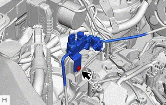
INSTALL ENGINE WIRE (for 2GR-FKS)
-
Install the engine wire with the 3 bolts.
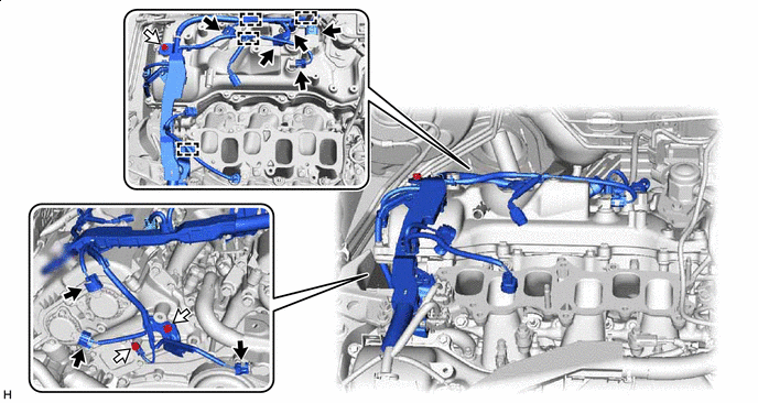

Connector 
Bolt - Torque:
- 8.35 N*m { 85 kgf*cm, 74 in.*lbf }
-
Engage the 4 clamps and connect the 8 connectors.
-
-
INSTALL INJECTOR VIBRATION INSULATOR (for 2GR-FKS)
-
INSTALL NO. 1 DELIVERY PIPE SPACER (for 2GR-FKS)
-
INSTALL FUEL DELIVERY PIPE SUB-ASSEMBLY (for 2GR-FKS)
-
CONNECT FUEL TUBE SUB-ASSEMBLY (for 2GR-FKS)
-
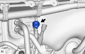
CONNECT NO. 2 VENTILATION HOSE (for 2GR-FKS)
-
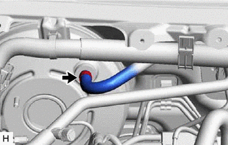
Connect the No. 2 ventilation hose to the cylinder head cover sub-assembly and slide the clip to secure it.
-
-
CONNECT AIR CONDITIONER TUBE AND ACCESSORY ASSEMBLY (w/o Sub-cool Accelerator)
-
for 2GR-FKS with Rear Air Conditioning System:
-
Remove the vinyl tape from the air conditioner tube and accessory assembly.
-
Sufficiently apply compressor oil to 2 new O-rings and the fitting surface of the air conditioner tube and accessory assembly.
Compressor Oil ND-OIL 8 or equivalent -
Install the 2 O-rings to the air conditioner tube and accessory assembly.
-
Connect the air conditioner tube and accessory assembly to the air conditioning hose and accessory.
Note
Do not deform the refrigerant lines.
-
Install the piping clamp to the air conditioner tube and accessory assembly.
-
-
-
CONNECT SUCTION PIPE SUB-ASSEMBLY (w/o Sub-cool Accelerator)
-
for 2GR-FKS with Rear Air Conditioning System:
-
Remove the vinyl tape from the suction pipe sub-assembly.
-
Sufficiently apply compressor oil to 2 new O-rings and the fitting surface of the suction pipe sub-assembly.
Compressor Oil ND-OIL 8 or equivalent -
Install the 2 O-rings to the suction pipe sub-assembly.
-
Connect the suction pipe sub-assembly to the air conditioning hose and accessory.
Note
Do not deform the refrigerant lines.
-
Install the piping clamp to the suction pipe sub-assembly.
-
-
-
CONNECT AIR CONDITIONER TUBE AND ACCESSORY ASSEMBLY (w/o Sub-cool Accelerator)
-
Remove the vinyl tape from the air conditioner tube and accessory assembly.
-
Sufficiently apply compressor oil to a new O-ring and the fitting surface of the air conditioner tube and accessory assembly.
Compressor Oil ND-OIL 8 or equivalent -
Install the O-ring to the air conditioner tube and accessory assembly.
-
Insert the air conditioner tube and accessory assembly to the air conditioning unit assembly.
-
for 2GR-FKS:
-
Engage the clamp to install the air conditioner tube and accessory assembly.
Note
-
Do not deform the refrigerant lines.
-
Do not damage the clamp.
-
-
Install the air conditioner tube and accessory assembly with the bolt.
- Torque:
- 9.8 N*m { 100 kgf*cm, 87 in.*lbf }
Note
Do not deform the refrigerant lines.
-
Engage the clamp.
-
Connect the connector to the air conditioner tube and accessory assembly.
-
-
for 8AR-FTS:
-
Install the air conditioner tube and accessory assembly with the bolt.
- Torque:
- 9.8 N*m { 100 kgf*cm, 87 in.*lbf }
Note
Do not deform the refrigerant lines.
-
Engage the clamp to install the air conditioner tube and accessory assembly.
Note
-
Do not deform the refrigerant lines.
-
Do not damage the clamp.
-
-
-
-
INSTALL SUCTION PIPE SUB-ASSEMBLY (w/o Sub-cool Accelerator)
-
Remove the vinyl tape from the suction pipe sub-assembly.
-
Sufficiently apply compressor oil to a new O-ring and the fitting surface of the suction pipe sub-assembly.
Compressor Oil ND-OIL 8 or equivalent -
Install the O-ring to the suction pipe sub-assembly.
-
Insert the suction pipe sub-assembly to the air conditioning unit assembly.
-
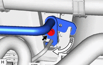
Rotate the hook connector as shown in the illustration.
-
Insert the tube joint into the fitting hole securely and install the bolt.
- Torque:
- 9.8 N*m { 100 kgf*cm, 87 in.*lbf }
-
for 8AR-FTS:
-
Engage the clamp to install the suction pipe sub-assembly.
Note
-
Do not deform the refrigerant lines.
-
Do not damage the clamp.
-
-
Engage the clamp to the suction pipe sub-assembly.
-
-
for 2GR-FKS:
-
Engage the clamp to install the suction pipe sub-assembly.
Note
-
Do not deform the refrigerant lines.
-
Do not damage the clamp.
-
-
Engage the clamp to the suction pipe sub-assembly.
-
-
-
INSTALL NO. 2 AIR CONDITIONER TUBE AND ACCESSORY ASSEMBLY (w/ Sub-cool Accelerator)
-
Remove the vinyl tape from the No. 2 air conditioner tube and accessory assembly.
-
Sufficiently apply compressor oil to 2 new O-rings and the fitting surface of the No. 2 air conditioner tube and accessory assembly.
Compressor Oil ND-OIL 12 or equivalent -
Install the 2 O-rings to the No. 2 air conditioner tube and accessory assembly.
-
Insert the No. 2 air conditioner tube and accessory assembly to the air conditioning unit assembly.
-
Rotate the hook connector as shown in the illustration.
-
Insert the tube joint into the fitting hole securely and install the bolt.
- Torque:
- 9.8 N*m { 100 kgf*cm, 87 in.*lbf }
-
Install the No. 2 air conditioner tube and accessory assembly with the bolt.
Note
Do not deform the refrigerant lines.
-
-
CONNECT AIR CONDITIONER TUBE AND ACCESSORY ASSEMBLY (w/ Sub-cool Accelerator)
-
Remove the vinyl tape from the air conditioner tube and accessory assembly.
-
Sufficiently apply compressor oil to 2 new O-rings and the fitting surface of the air conditioner tube and accessory assembly.
Compressor Oil ND-OIL 12 or equivalent -
Install the 2 O-rings to the air conditioner tube and accessory assembly.
-
Connect the air conditioner tube and accessory assembly to the No. 2 air conditioner tube and accessory assembly.
Note
Do not deform the refrigerant lines.
-
Install the air conditioner tube and accessory assembly with the bolt.
Note
Do not deform the refrigerant lines.
- Torque:
- 9.8 N*m { 100 kgf*cm, 87 in.*lbf }
-
Install the piping clamp to the air conditioner tube and accessory assembly.
-
-
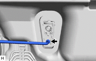
CONNECT SUCTION HOSE SUB-ASSEMBLY (w/ Sub-cool Accelerator)
-
Remove the vinyl tape from the suction hose sub-assembly.
-
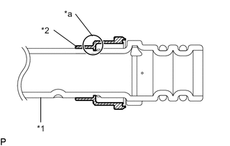
*1 Suction Hose Sub-assembly *2 Piping Clamp *a Groove Install a new piping clamp to the suction hose sub-assembly.
Note
-
Securely engage the inside step of the piping clamp into the groove of the suction hose sub-assembly.
-
Do not widen the opening of the piping clamp more than the diameter of the suction hose sub-assembly when installing it.
-
Do not install the piping clamp with the large diameter section in the wrong direction.
-
-
Sufficiently apply compressor oil to 2 new O-rings and the fitting surface of the suction hose sub-assembly.
Compressor Oil ND-OIL 12 or equivalent -
Install the 2 O-rings to the suction hose sub-assembly
-
Connect the suction hose sub-assembly to the No. 2 air conditioner tube and accessory assembly.
Note
Do not deform the refrigerant lines.
-
-
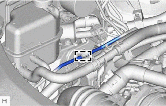
INSTALL BRAKE LINE
-
Install the front No. 6 brake tube and front No. 7 brake tube, and engage the 2 clamps to secure the 2 brake lines.
Note
-
Do not damage the 2 clamps.
-
Do not kink or damage the brake lines.
-
-
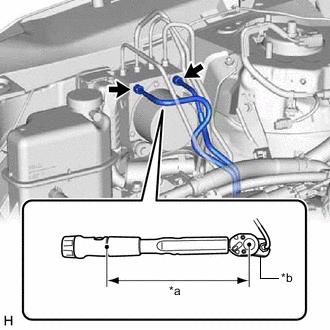
*a Torque Wrench Fulcrum Length *b Union Nut Wrench Using a union nut wrench, connect the No. 6 brake tube and front No. 7 brake tube to the brake actuator assembly.
- Torque:
- Specified tightening torque
- 19.5 N*m { 199 kgf*cm, 14 ft.*lbf }
Note
-
Do not kink or damage the brake lines.
-
Do not allow the brake lines to twist or interfere with other parts or the vehicle body during tightening.
-
Do not allow any foreign matter such as dirt or dust to enter the brake lines from the connecting parts.
Tech Tips
-
Calculate the torque wrench reading when changing the fulcrum length of the torque wrench.
-
When using a union nut wrench (fulcrum length of 20 mm (0.787 in.)) + torque wrench (fulcrum length of 162 mm (6.38 in.)):
17.36 N*m (177 kgf*cm, 13 ft.*lbf)
-
-
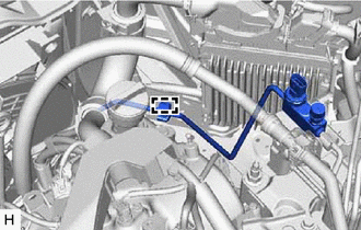
INSTALL ENGINE ROOM MAIN WIRE
-
Engage the 8 clamps to install the engine room main wire.
-
for 8AR-FTS:
-
Connect the connector to the vacuum sensor assembly.
-
-
for 2GR-FKS:
-
Connect the connector to the vacuum warning switch assembly.
-
-
-
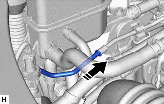
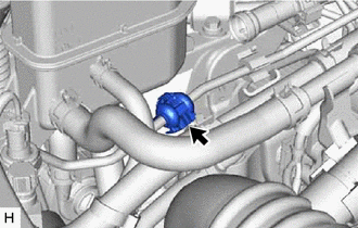
CONNECT CHECK VALVE TO BRAKE BOOSTER HOSE (for 8AR-FTS)
-
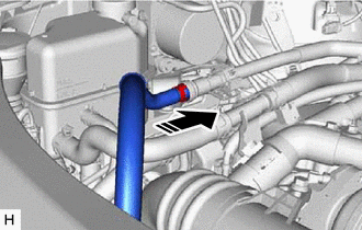
Connect the check valve to brake booster hose to the brake booster assembly, and slide the clip to secure it.
-
-
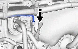
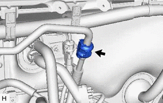
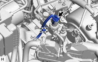
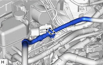
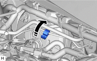
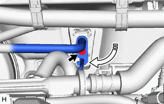
CONNECT UNION TO CHECK VALVE HOSE (for 2GR-FKS)
-
w/o Rear Air Conditioning System:
-
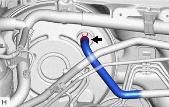
Connect the union to check valve hose to the brake booster assembly, and slide the clip to secure it.
-
-
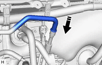
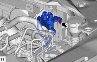
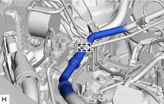
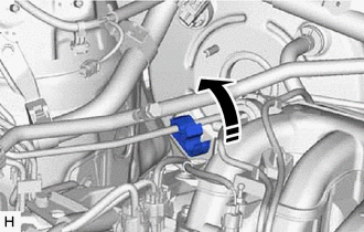
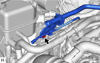
w/ Rear Air Conditioning System:
-
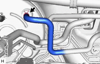
Connect the union to check valve hose to the brake booster assembly, and slide the clip to secure it.
-
-
-
INSTALL NO. 1 ENGINE COVER SUB-ASSEMBLY (for 8AR-FTS)
-
INSTALL BRAKE MASTER CYLINDER SUB-ASSEMBLY WITH WAY
-
INSTALL FUEL PUMP ASSEMBLY (for 2GR-FKS)
-
CONNECT CABLE TO NEGATIVE BATTERY TERMINAL
Note
When disconnecting the cable, some systems need to be initialized after the cable is reconnected
-
CHARGE AIR CONDITIONING SYSTEM WITH REFRIGERANT
for HFC-134a (R134a): Click here
for HFO-1234yf (R1234yf): Click here
-
WARM UP ENGINE
for HFC-134a (R134a): Click here
for HFO-1234yf (R1234yf): Click here
-
INSPECT FOR REFRIGERANT LEAK
for HFC-134a (R134a): Click here
for HFO-1234yf (R1234yf): Click here
-
INSPECT AND ADJUST BRAKE PEDAL
-
INSTALL NO. 1 INSTRUMENT PANEL UNDER COVER SUB-ASSEMBLY
-
INSTALL COWL SIDE TRIM BOARD RH
-
INSTALL FRONT DOOR SCUFF PLATE RH
Tech Tips
Use the same procedure as for the LH side.
w/o Rear No. 2 Seat: Click here
w/ Rear No. 2 Seat: Click here