FRONT DOOR LOCK REMOVAL
CAUTION / NOTICE / HINT
The necessary procedures (adjustment, calibration, initialization, or registration) that must be performed after parts are removed, installed, or replaced during the front door lock assembly removal/installation are shown below.
| Replacement Part | Necessary Procedure | Effect/Inoperative Function When Necessary Procedures are not Performed | Link |
|---|---|---|---|
| Removal and installation of battery terminal | Drive the vehicle until stop and start control is permitted (approximately 5 to 60 minutes) | Stop and start system | for 8GR-FKS: Click here for V35A-FTS: Click here |
| Memorize steering angle neutral point | LKA/LDA system | ||
| Parking support brake system* | |||
| Pre-collision system | |||
| Adaptive high beam system | |||
Lighting system (EXT) |
|||
| Variable gear ratio steering system | |||
| Parking assist monitor system | |||
| Panoramic view monitor system | |||
| Initialize Rear Door Sunshade System | Rear door sunshade system | ||
| Initialize power trunk lid system | Power trunk lid system | ||
|
Side television camera view adjustment | Panoramic view monitor system | |
|
Initialize power window control system |
|
Click here Click here
Tech Tips
-
Use the same procedure for RHD and LHD vehicles.
-
The procedure listed below is for LHD vehicles.
-
Use the same procedure for the RH and LH sides.
-
The procedure listed below is for the LH side.
-
When removing the front door glass sub-assembly LH, move the front door glass sub-assembly LH to the lowest position before disconnecting the battery negative (-) terminal.
PROCEDURE
-
PRECAUTION
Note
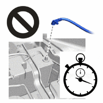
After turning the engine switch off, waiting time may be required before disconnecting the cable from the negative (-) battery terminal. Therefore, make sure to read the disconnecting the cable from the negative (-) battery terminal notices before proceeding with work.
-
REMOVE LUGGAGE COMPARTMENT MAT SUB-ASSEMBLY
-
DISCONNECT CABLE FROM NEGATIVE BATTERY TERMINAL
for 8GR-FKS:
for V35A-FTS:
CAUTION:
-
Wait at least 90 seconds after disconnecting the cable from the negative(-) battery terminal to disable the SRS system.
-
If the airbag deploys for any reason, it may cause a serious accident.
Note
When disconnecting the cable, some systems need to be initialized after the cable is reconnected.
-
-
REMOVE FRONT DOOR TRIM UPPER COVER LH
-
REMOVE FRONT DOOR ARMREST COVER LH
-
REMOVE FRONT DOOR NO. 2 ARMREST COVER LH
-
REMOVE FRONT DOOR TRIM BOARD SUB-ASSEMBLY LH
-
REMOVE FRONT DOOR TRIM COVER LH
-
REMOVE UPPER DOOR FRAME GARNISH LH
-
REMOVE FRONT DOOR GLASS INNER WEATHERSTRIP LH
-
REMOVE FRONT DOOR VENT SEAL LH
-
REMOVE FRONT DOOR PANEL PROTECTOR LH
-
REMOVE FRONT NO. 1 SPEAKER ASSEMBLY
-
REMOVE FRONT DOOR SERVICE HOLE COVER LH
-
REMOVE OUTER MIRROR INSTALL HOLE COVER LH
-
REMOVE FRONT MULTIPLEX NETWORK DOOR ECU LH
-
REMOVE OUTER REAR VIEW MIRROR ASSEMBLY LH
-
REMOVE DOOR SIDE AIRBAG SENSOR LH
-
REMOVE FRONT DOOR ARMREST SET BRACKET LH
-
REMOVE FRONT DOOR NO. 3 WEATHERSTRIP LH
-
REMOVE FRONT DOOR NO. 2 WEATHERSTRIP LH
-
REMOVE FRONT DOOR BELT MOULDING LH
-
REMOVE FRONT DOOR REAR BELT MOULDING END COVER LH
-
REMOVE FRONT DOOR WINDOW FRAME MOULDING LH(CENTER PILLAR SIDE)
-
REMOVE FRONT PILLAR UPPER COVER SUB-ASSEMBLY LH
-
REMOVE FRONT DOOR GLASS RUN LH
-
REMOVE FRONT DOOR FRONT GLASS RUN LH
-
REMOVE FRONT DOOR GLASS SUB-ASSEMBLY LH
-
REMOVE FRONT DOOR REAR LOWER FRAME SUB-ASSEMBLY LH
-
REMOVE FRONT DOOR NO. 2 GLASS RUN LH
-
REMOVE FRONT DOOR REAR WINDOW FRAME LH
-
REMOVE FRONT DOOR UPPER WINDOW FRAME MOULDING LH
-
REMOVE FRONT DOOR FRONT WINDOW FRAME MOULDING LH
-
REMOVE FRONT DOOR WINDOW REGULATOR ASSEMBLY LH
-
REMOVE FRONT DOOR OUTSIDE HANDLE ASSEMBLY LH (for Driver Side)
-
REMOVE FRONT DOOR LOCK CYLINDER ASSEMBLY LH (for Driver Side)
-
REMOVE FRONT DOOR LOCK WITH MOTOR ASSEMBLY LH
-
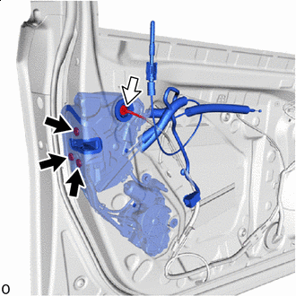

"TORX" screw 
Connector Disconnect the connector.
-
Using a T30 "TORX" socket wrench, remove the 3 TORX screws.
-

Remove in this Direction Remove the 2 bolts and front door lock with motor assembly LH in the direction indicated by the arrow shown in the illustration.
Note
Do not damage the vehicle body with front door lock with motor assembly LH.
Tech Tips
Remove the front door lock with motor assembly LH while supporting it with one hand.
-
When reusing front door lock with motor assembly LH:
-
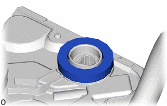
Remove the door lock wire harness seal from the front door lock with motor assembly LH.
-
-
-
REMOVE FRONT DOOR LOCK COVER SUB-ASSEMBLY LH
-
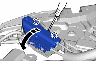
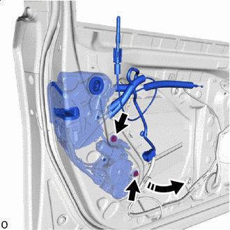
Remove in this Direction 
Protective Tape Using a thin-bladed screwdriver, detach the claw and open the front door lock cover sub-assembly LH.
-

Detach the claw and remove the front door lock cover sub-assembly LH.
-
-
REMOVE FRONT DOOR LOCK REMOTE CONTROL CABLE ASSEMBLY LH
-
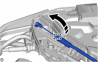
Remove in this Direction As shown in the illustration, detach the clamp and remove the front door lock remote control cable assembly LH.
-
-
REMOVE FRONT DOOR INSIDE LOCKING CABLE ASSEMBLY LH
-
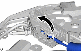
Remove in this Direction As shown in the illustration, detach the clamp and remove the front door inside locking cable assembly LH.
-