FRONT DIFFERENTIAL SIDE GEAR SHAFT OIL SEAL REPLACEMENT

CAUTION / NOTICE / HINT
The necessary procedures (adjustment, calibration, initialization, or registration) that must be performed after parts are removed and installed, or replaced during the front differential side gear shaft oil seal removal/installation are shown below.
| Replacement Part or Procedure | Necessary Procedure | Effect/Inoperative when not Performed | Link |
|---|---|---|---|
| Disconnect cable from negative battery terminal | Drive the vehicle until stop and start control is permitted (approximately 5 to 60 minutes) | Stop and start system | |
| Memorize steering angle neutral point | LKA/LDA system | ||
| Parking support brake system*1 | |||
| Pre-collision system | |||
| Adaptive high beam system | |||
Lighting system (EXT) |
|||
| Variable gear ratio steering system | |||
| Parking assist monitor system | |||
| Panoramic view monitor system | |||
| Initialize rear door sunshade system | Rear door sunshade system | ||
| Initialize power trunk lid system | Power trunk lid system | ||
|
Inspection after repair |
|
w/ Canister Pump Module: w/o Canister Pump Module: Click here |
| Engine assembly | Inspection after repair |
|
w/ Canister Pump Module: Click here w/o Canister Pump Module: Click here |
|
|
||
| w/ Stop and Start System: Starter assembly Note When the starter assembly is replaced, "ST NO. 1 relay" and "ST NO. 2 relay" must be also replaced. |
Clear number of starter operations | Stop and start system | |
| Automatic transmission assembly with transfer |
|
|
for Initialization: Click here for Registration: Click here |
| Automatic transmission fluid | ATF thermal degradation estimate reset | The value of the Data List item "ATF Thermal Degradation Estimate" is not estimated correctly. | |
| Parts between the steering wheel and tires have been removed/installed, replaced or adjusted | Perform actuator angle neutral point calibration and initialization |
|
|
| Front bumper assembly (Including removal and installation) |
|
Parking support brake system | |
| Front television camera view adjustment | Panoramic view monitor system | ||
| Suspension, tires, etc. |
|
Parking support brake system | |
|
Panoramic view monitor system | ||
| Rear television camera assembly optical axis (Back camera position setting) | Parking assist monitor system |
Click here Click here
*2: New automatic transmission's compensation code.
Note
After the engine switch is turned off, the radio receiver assembly records various types of memory and settings. As a result, after turning the engine switch off, be sure to wait for the time specified in the following table before disconnecting the cable from the negative (-) battery terminal.
| System Name | See Procedure |
|---|---|
| Vehicle enrolled in lexus enform system or safety connect system | 6 minutes |
| Vehicle not enrolled in lexus enform system and safety connect system | 1 minute |
CAUTION:
-
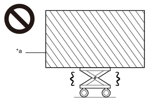
*a Heavy object exceeding the capacity of the engine lifter Because the weight of the engine with transmission assembly is extremely heavy, make sure to follow the work procedures described in the repair manual.
-
If work is not performed according to the procedures described in the repair manual, there is a danger that the engine lifter could drop and components could fall down.
-
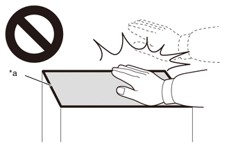
*a High temperature areas Do not touch the engine or exhaust manifold sub-assembly when they are hot.
-
Touching the engine or exhaust manifold sub-assembly when they are hot could result in burns.
-
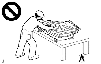
Never perform work on fuel system components near any possible ignition sources.
-
Vaporized fuel could ignite, resulting in a serious accident.
-
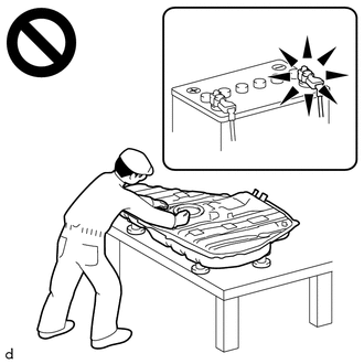
Do not perform work on fuel system components without first disconnecting the cable from the negative (-) battery terminal.
-
Sparks could cause vaporized fuel to ignite, resulting in a serious accident.
Note
This procedure includes the removal of small-head bolts. Refer to Small-Head Bolts of Basic Repair Hint to identify the small-head bolts.
PROCEDURE
-
PRECAUTION
-
REMOVE ENGINE AND TRANSMISSION
-
REMOVE PROPELLER SHAFT HEAT INSULATOR
-
REMOVE FRONT DIFFERENTIAL CARRIER ASSEMBLY
-
FIX FRONT DIFFERENTIAL CARRIER ASSEMBLY
-
REMOVE FRONT DRIVE SHAFT OIL SEAL RH
-
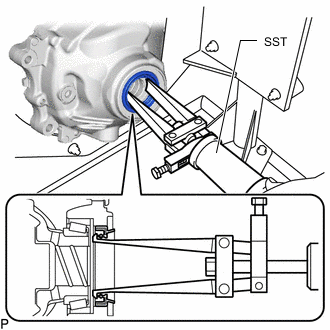
Using SST, remove the front differential case oil seal LH.
- SST
- 09308-00010
-
-
REMOVE FRONT DRIVE SHAFT OIL SEAL LH
-
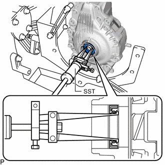
Using SST, remove the front differential case oil seal RH.
- SST
- 09308-00010
-
-
INSTALL FRONT DRIVE SHAFT OIL SEAL RH
-
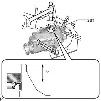
*a 24 to 25 mm (0.945 to 0.984 in.)
(From the end of the front differential carrier)
Using SST and a hammer, install a new front differential case oil seal RH.
- SST
- 09608-32010
- 09950-70010 ( 09951-07100 )
Standard depth 24.0 to 25.0 mm (0.9450 to 0.984 in.) (From the end of the front differential carrier) Note
-
Tap the front differential case oil seal uniformly so that the front differential case oil seal is straight.
-
Do not excessively tap the front differential case oil seal.
-
Make sure the difference between the maximum and minimum measured values is less than 0.47 mm (0.0185 in.), as a greater difference may lead to oil leaks.
-
Using a vernier caliper, measure the depth of the front drive shaft oil seal RH.
-
-
INSTALL FRONT DRIVE SHAFT OIL SEAL LH
-
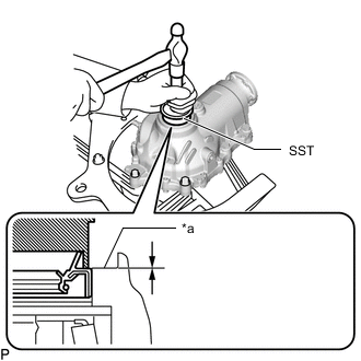
*a -0.5 to 0.5 mm (-0.0197 to 0.0196 in.) Using SST and a hammer, install a new front differential case oil seal RH.
- SST
- 09608-32010
- 09950-70010 ( 09951-07100 )
Standard depth -0.5 to 0.5 mm (-0.0197 to 0.0196 in.) Note
-
Tap the front differential case oil seal uniformly so that the front differential case oil seal is straight.
-
Do not excessively tap the front differential case oil seal.
-
Make sure the difference between the maximum and minimum measured values is less than 0.47 mm (0.0185 in.), as a greater difference may lead to oil leaks.
-
Using a vernier caliper, measure the depth of the front drive shaft oil seal RH.
-
-
REMOVE FRONT DIFFERENTIAL CARRIER ASSEMBLY
-
INSTALL FRONT DIFFERENTIAL CARRIER ASSEMBLY
-
INSTALL PROPELLER SHAFT HEAT INSULATOR
-
INSTALL ENGINE AND TRANSMISSION