ENGINE STOP AND START ECU REMOVAL
CAUTION / NOTICE / HINT
Tech Tips
-
Use the same procedure for RHD and LHD vehicles.
-
The procedure listed below is for LHD vehicles.
The necessary procedures (adjustment, calibration, initialization, or registration) that must be performed after parts are removed, installed, or replaced during the engine stop and start ECU removal/installation are shown below.
| Replacement Part or Procedure | Necessary Procedure | Effect/Inoperative when not Performed | Link |
|---|---|---|---|
| Disconnect cable from negative battery terminal | Drive the vehicle until stop and start control is permitted (approximately 5 to 60 minutes) | Stop and start system | for 8GR-FKS: Click here for V35A-FTS: Click here |
| Memorize steering angle neutral point | LKA/LDA system | ||
| Parking support brake system* | |||
| Pre-collision system | |||
| Adaptive high beam system | |||
Lighting system (EXT) |
|||
| Variable gear ratio steering system | |||
| Parking assist monitor system | |||
| Panoramic view monitor system | |||
| Initialize rear door sunshade system | Rear door sunshade system | ||
| Initialize power trunk lid system | Power trunk lid system |
Click here Click here
Note
After the engine switch is turned off, the navigation system requires approximately a minute to record various types of memory and settings. As a result, after turning the engine switch off, wait a minute or more before disconnecting the cable from the negative (-) battery terminal.
PROCEDURE
-
READ NUMBER OF STARTER OPERATIONS
-
for 8GR-FKS:
-
for V35A-FTS:
-
-
PRECAUTION
Note
After turning the engine switch off, waiting time may be required before disconnecting the cable from the battery terminal. Therefore, make sure to read the disconnecting the cable from the battery terminal notice before proceeding with work.
-
DISCONNECT CABLE FROM NEGATIVE BATTERY TERMINAL
Note
When disconnecting the cable, some systems need to be initialized after the cable is reconnected.
-
REMOVE INSTRUMENT SIDE PANEL RH (for LHD)
-
REMOVE INSTRUMENT SIDE PANEL LH (for RHD)
-
REMOVE NO. 2 INSTRUMENT PANEL UNDER COVER SUB-ASSEMBLY
-
REMOVE NO. 2 INSTRUMENT PANEL SAFETY PAD SUB-ASSEMBLY
-
REMOVE LOWER INSTRUMENT PANEL FINISH PANEL ASSEMBLY
-
REMOVE INSTRUMENT PANEL SAFETY PAD INSERT SUB-ASSEMBLY
-
REMOVE INSTRUMENT CLUSTER FINISH PANEL GARNISH ASSEMBLY
-
REMOVE LOWER NO. 2 INSTRUMENT PANEL AIRBAG ASSEMBLY
-
REMOVE GLOVE COMPARTMENT DOOR ASSEMBLY
-
REMOVE ENGINE STOP AND START ECU (for LHD)
-
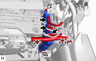

Connector 
Bolt 
Nut Detach the clamps and disconnect the connectors.
-
Remove the bolt, nut and engine stop and start ECU.
-
-
REMOVE ENGINE STOP AND START ECU (for RHD)
-
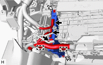
Connector Bolt Nut Detach the clamps and disconnect the connectors.
-
Remove the bolt, nut and engine stop and start ECU.
-