OIL PUMP REMOVAL

CAUTION / NOTICE / HINT
The necessary procedures (adjustment, calibration, initialization, or registration) that must be performed after parts are removed, installed, or replaced during the timing chain cover assembly removal/installation are shown below.
| Replaced Part or Performed Procedure | Necessary Procedure | Effect/Inoperative Function when Necessary Procedure not Performed | Link |
|---|---|---|---|
| Battery terminal is disconnected/reconnected | Drive the vehicle until stop and start control is permitted (approximately 5 to 60 minutes) | Stop and start system | |
| Memorize steering angle neutral point | LKA/LDA system | ||
| Parking support brake system* | |||
| Pre-collision system | |||
| Adaptive high beam system | |||
Lighting system (EXT) |
|||
| Variable gear ratio steering system | |||
| Parking assist monitor system | |||
| Panoramic view monitor system | |||
| Initialize rear door sunshade system | Rear door sunshade system | ||
| Initialize power trunk lid system | Power trunk lid system | ||
|
Inspection after repairs |
|
w/ Canister Pump Module: w/o Canister Pump Module: |
Click here Click here
Note
After the engine switch is turned off, the navigation system requires approximately a minute to record various types of memory and settings. As a result, after turning the engine switch off, wait a minute or more before disconnecting the cable from the negative (-) battery terminal.
| System Name | See Procedure |
|---|---|
| Vehicle enrolled in telematics system (for G-BOOK) | 6 minutes |
| Vehicle not enrolled in telematics system (for G-BOOK) | 1 minute |
Note
This procedure includes the removal of small-head bolts. Refer to Small-Head Bolts of Basic Repair Hint to identify the small-head bolts.
PROCEDURE
-
REMOVE COMPRESSOR ASSEMBLY WITH PULLEY
-
for 2WD:
-
for AWD:
-
-
REMOVE GENERATOR ASSEMBLY
-
REMOVE FUEL PUMP ASSEMBLY (for Bank 1)
-
REMOVE FUEL PUMP ASSEMBLY (for Bank 2)
-
REMOVE ENGINE OIL LEVEL DIPSTICK GUIDE
-
DISCONNECT NO. 1 PCV TUBE
-
REMOVE NO. 1 AIR INLET DUCT
-
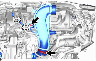
Detach the 2 clamps and disconnect the vacuum hose.
-
Remove the bolt.
-
Loosen the hose clamp and remove the No. 1 air inlet duct from the inlet compressor elbow.
-
-
REMOVE NO. 1 AIR HOSE
-
Loosen the hose clamp and remove the No. 1 air hose from the outlet compressor elbow.
-
-
DISCONNECT NO. 2 PCV TUBE
-
REMOVE NO. 2 AIR INLET DUCT
-
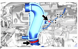
Detach the 2 clamps and disconnect the vacuum hose.
-
Remove the bolt.
-
Loosen the hose clamp and remove the No. 2 air inlet duct from the inlet compressor elbow.
-
-
REMOVE TURBO WATER PIPE STAY
-
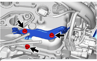
Remove the 3 bolts and turbo water pipe stay.
-
-
DISCONNECT NO. 1 TURBO WATER PIPE SUB-ASSEMBLY
-
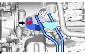
Remove the bolt and disconnect the No. 1 turbo water pipe sub-assembly from the cylinder head cover sub-assembly RH.
-
-
DISCONNECT WATER HOSE
-
DISCONNECT NO. 1 WATER BY-PASS PIPE
-
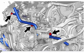
Remove the 3 bolts and disconnect the No. 1 water by-pass pipe.
Tech Tips
Leave the No. 1 water by-pass pipe on the engine side.
-
-
REMOVE NO. 1 TURBO PRESSURE SENSOR
-
REMOVE INTAKE PIPE STAY
-
REMOVE WATER CONTROL VALVE
-
REMOVE NO. 2 WATER BY-PASS PIPE SUB-ASSEMBLY
-
REMOVE NO. 11 ENGINE WIRE
-
REMOVE NO. 1 WATER OUTLET PIPE
-
REMOVE NO. 2 WATER OUTLET PIPE
-
REMOVE WATER OUTLET PIPE WATER BY-PASS JOINT
-
DISCONNECT NO. 4 RADIATOR HOSE
-
REMOVE WATER PUMP PULLEY
-
REMOVE IDLER PULLEY SUB-ASSEMBLY
-
REMOVE V-RIBBED BELT TENSIONER ASSEMBLY
-
REMOVE WATER INLET ASSEMBLY
-
REMOVE GENERATOR BRACKET SUB-ASSEMBLY
-
REMOVE IGNITION COIL ASSEMBLY
-
REMOVE OIL FILTER BRACKET SUB-ASSEMBLY
-
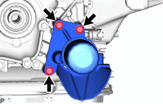
for 2WD:
-
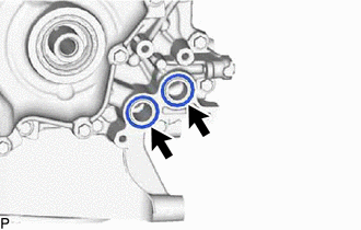
Remove the 3 bolts and oil filter bracket sub-assembly from the timing chain cover assembly.
-
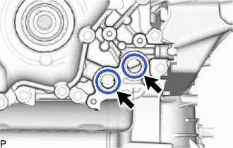
Remove the 2 O-rings from the timing chain cover assembly.
-
-
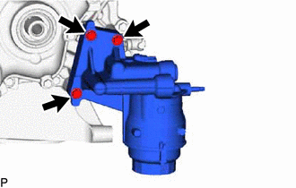
for AWD:
-
Remove the 3 bolts and oil filter bracket sub-assembly from the timing chain cover assembly.
-
Remove the 2 O-rings from the timing chain cover assembly.
-
-
-
REMOVE SPARK PLUG
-
REMOVE NO. 2 ENGINE COVER LH
-
REMOVE NO. 2 ENGINE COVER RH
-
REMOVE CYLINDER HEAD COVER SUB-ASSEMBLY LH
-
Remove the No. 1 intercooler air guide from the cylinder head cover sub-assembly LH.
-
Remove the 2 bolts and 2 VVT sensors.
-
Remove the 14 bolts and cylinder head cover sub-assembly LH.
-
Remove the camshaft bearing cap oil hole gasket LH.
-
Remove the 6 gaskets and No. 1 cylinder head cover gasket LH.
-
-
REMOVE CYLINDER HEAD COVER SUB-ASSEMBLY RH
-
Remove the No. 1 intercooler air guide from the cylinder head cover sub-assembly RH.
-
Remove the 2 bolts and 2 VVT sensors.
-
Remove the 14 bolts and cylinder head cover sub-assembly RH.
-
Remove the camshaft bearing cap oil hole gasket RH.
-
Remove the 6 gaskets and No. 1 cylinder head cover gasket RH.
-
-
REMOVE SPARK PLUG TUBE GASKET
-
REMOVE CAM TIMING OIL CONTROL SOLENOID ASSEMBLY RH
-
REMOVE CAM TIMING OIL CONTROL SOLENOID ASSEMBLY LH
-
REMOVE CAM TIMING CONTROL MOTOR WITH EDU ASSEMBLY RH
-
REMOVE CAM TIMING CONTROL MOTOR WITH EDU ASSEMBLY LH
-
REMOVE CRANKSHAFT PULLEY COVER
-
REMOVE CRANKSHAFT DAMPER SUB-ASSEMBLY
-
REMOVE CRANKSHAFT PULLEY
-
SET NO. 1 CYLINDER TO TDC/COMPRESSION
-
REMOVE TIMING CHAIN CASE OIL SEAL
-
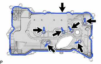
REMOVE TIMING CHAIN OR BELT COVER SUB-ASSEMBLY
-
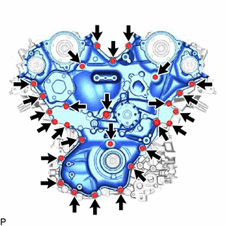
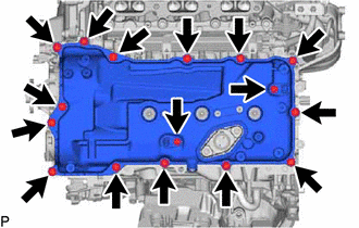
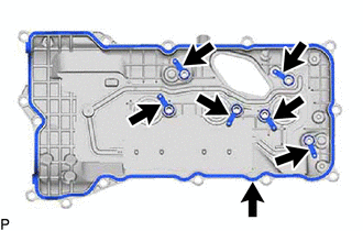
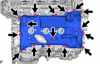
Remove the 27 bolts shown in the illustration.
-
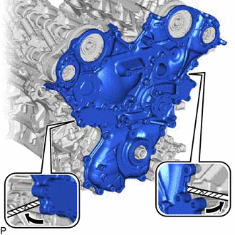
Remove the timing chain or belt cover sub-assembly by prying between the timing chain or belt cover sub-assembly and timing chain cover assembly with a screwdriver.
Note
Be careful not to damage the contact surfaces of the timing chain or belt cover sub-assembly and timing chain cover assembly.
Tech Tips
Tape the screwdriver tip before use.
-
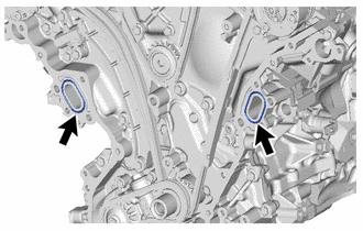
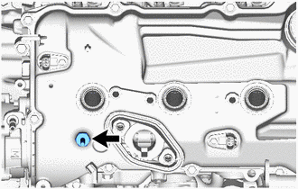
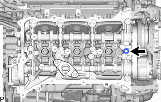
Remove the 2 water pump gaskets from the timing chain cover assembly.
-
-
REMOVE OIL PUMP DRIVE CHAIN SUB-ASSEMBLY
-
Using the hexagonal portion of the camshaft, secure the camshaft.
-
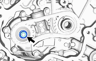
Loosen the oil pump drive shaft gear nut.
-
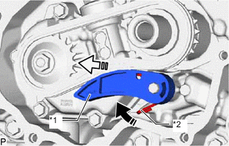
*1 Chain Tensioner Plate *2 Chain Damper Spring 
Push 
Remove in this Direction While pushing the chain damper spring, remove the chain tensioner plate and chain damper spring as shown in the illustration.
-
Remove the oil pump drive shaft gear nut.
-
Remove the oil pump drive sprocket, oil pump drive shaft sprocket and oil pump drive chain sub-assembly.
-
-
REMOVE NO. 1 CHAIN TENSIONER ASSEMBLY
-
REMOVE CHAIN TENSIONER SLIPPER
-
REMOVE NO. 1 CHAIN SUB-ASSEMBLY
-
REMOVE IDLE SPROCKET ASSEMBLY
-
REMOVE NO. 1 CHAIN VIBRATION DAMPER
-
REMOVE NO. 2 CHAIN VIBRATION DAMPER
-
REMOVE CRANKSHAFT TIMING GEAR OR SPROCKET
-
REMOVE TIMING CHAIN COVER ASSEMBLY
-
REMOVE NO. 6 ENGINE COVER