MANUAL TRANSAXLE ASSEMBLY(When Using the Engine Support Bridge) REMOVAL

CAUTION / NOTICE / HINT
The necessary procedures (adjustment, calibration, initialization, or registration) that must be performed after parts are removed, installed, or replaced during the manual transaxle assembly removal/installation are shown below.
| Replacement Part or Procedure | Necessary Procedure | Effect/Inoperative when not Performed | Link |
|---|---|---|---|
| Disconnect cable from negative battery terminal | Memorize steering angle neutral point |
|
|
| Initialize back door lock | Power door lock control system | ||
| Front wheel alignment adjustment | w/ VSC: Perform the following procedures in the order shown:
|
|
-
*1: When performing learning using the GTS.
CAUTION:
-
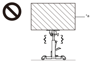
*a Heavy object exceeding the capacity of the transmission jack Because the manual transaxle assembly is extremely heavy, make sure to follow the work procedures described in the repair manual.
-
If work is not performed according to the procedures described in the repair manual, there is a danger that the transmission jack could drop and components could fall down.
-
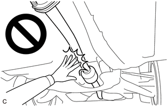
When the engine is hot, do not touch high-temperature areas such as the engine or exhaust pipe.
-
Touching high-temperature areas such as the engine and exhaust pipe could result in burns.
Note
When the manual transaxle assembly is removed, be sure to use a new clutch release cylinder with bearing assembly and new installation bolts. Removal of the manual transaxle assembly allows the compressed clutch release cylinder with bearing assembly to return to its original position. Dust from the moving section may damage the seal of the clutch release cylinder with bearing assembly, possibly causing clutch fluid leaks.
PROCEDURE
-
PRECAUTION
Note
After turning the ignition switch off, waiting time may be required before disconnecting the cable from the negative (-) battery terminal. Therefore, make sure to read the disconnecting the cable from the negative (-) battery terminal notices before proceeding with work.
-
DISCONNECT CABLE FROM NEGATIVE BATTERY TERMINAL
Note
When disconnecting the cable, some systems need to be initialized after the cable is reconnected.
-
ALIGN FRONT WHEELS FACING STRAIGHT AHEAD
-
REMOVE FRONT WHEELS
-
REMOVE NO. 1 ENGINE UNDER COVER
-
REMOVE REAR ENGINE UNDER COVER LH
-
REMOVE REAR ENGINE UNDER COVER RH
-
REMOVE FRONT FLOOR COVER LH (w/ Cover)
-
REMOVE FRONT FLOOR COVER RH (w/ Cover)
-
DRAIN MANUAL TRANSAXLE OIL
-
REMOVE WINDSHIELD WIPER MOTOR AND LINK
-
REMOVE NO. 1 HEATER AIR DUCT SPLASH SHIELD SEAL
-
REMOVE WATER GUARD PLATE LH
-
REMOVE COWL BODY MOUNTING REINFORCEMENT LH
-
REMOVE COWL BODY MOUNTING REINFORCEMENT RH
-
REMOVE OUTER COWL TOP PANEL SUB-ASSEMBLY (for LHD)
-
REMOVE OUTER COWL TOP PANEL SUB-ASSEMBLY (for RHD)
-
REMOVE BATTERY
-
REMOVE RADIATOR COVER
-
REMOVE NO. 1 AIR CLEANER INLET
-
REMOVE AIR CLEANER CAP WITH AIR CLEANER HOSE
-
REMOVE AIR CLEANER CASE SUB-ASSEMBLY
-
REMOVE ECM
-
REMOVE BATTERY CLAMP SUB-ASSEMBLY
-
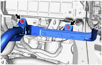
Remove the bolt and nut to separate the engine wire from the battery clamp sub-assembly.
-
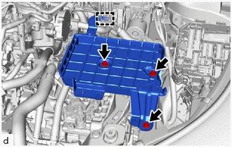
Disengage the clamp to separate the engine wire from the battery clamp sub-assembly.
-
Remove the 3 bolts and battery clamp sub-assembly from the vehicle.
-
-
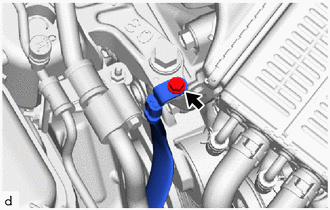
DISCONNECT TRANSMISSION CONTROL CABLE ASSEMBLY
-
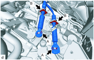
Remove the 2 clips A to disconnect the transmission control cable assembly from the manual transaxle assembly.
-
Remove the 2 clips B to disconnect the transmission control cable assembly from control cable bracket assembly.
-
-
SECURE STEERING WHEEL ASSEMBLY
-
REMOVE COLUMN HOLE COVER SILENCER SHEET
-
SEPARATE NO. 2 STEERING INTERMEDIATE SHAFT ASSEMBLY
-
SEPARATE NO. 1 STEERING COLUMN HOLE COVER SUB-ASSEMBLY
-
REMOVE FRONT FLOOR CENTER BRACE
-
REMOVE FRONT EXHAUST PIPE ASSEMBLY (TWC: Rear Catalyst)
-
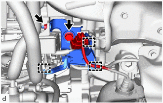
DISCONNECT WIRE HARNESS
-
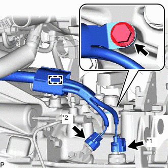
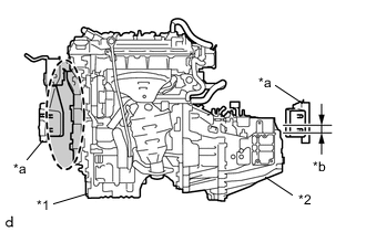
*1 Back-up Light Switch Assembly Connector *2 Transmission Revolution Sensor Connector Disconnect the back-up light switch assembly connector.
-
Disconnect the transmission revolution sensor connector.
-
Remove the bolt.
-
Disengage the clamp and separate the wire harness from the manual transaxle assembly.
-
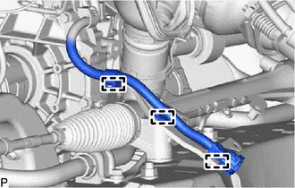
Disengage the 3 clamps and separate the heated oxygen sensor wire harness from the front suspension crossmember sub-assembly.
-
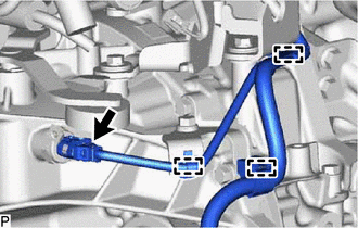
Disconnect the neutral position switch connector.
-
Disengage the 3 clamps and separate the wire harness from the manual transaxle assembly.
-
-
DISCONNECT NO. 1 CLUTCH HOSE
-
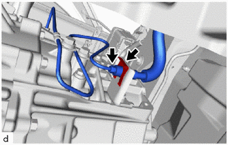
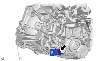
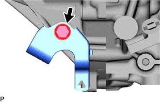
Using a 10 mm union nut wrench, disconnect the bleeder clutch release tube from the No. 1 clutch hose.
-
Remove the clip to disconnect the No. 1 clutch hose.
-
-
REMOVE DRIVE SHAFT HEAT INSULATOR SUB-ASSEMBLY
-
REMOVE FRONT DRIVE SHAFT ASSEMBLY (for TMC Made)
-
REMOVE FRONT DRIVE SHAFT ASSEMBLY (for TMMT Made)
-
INSTALL ENGINE HANGERS
-
Disconnect the wire harness from the wire harness clamp bracket.
-
Disengage the 3 clamps from the wire harness clamp bracket.
-
Remove the nut to separate the engine wire from the wire harness clamp bracket.
-
Remove the bolt and wire harness clamp bracket from the cylinder head sub-assembly.
-
Separate the bolts and No. 2 earth wire from the engine mounting insulator sub-assembly RH.
-
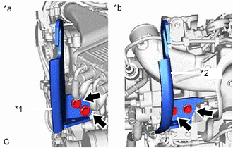
*1 No. 1 Engine Hanger (Part No. 12281-47060) *2 No. 2 Engine Hanger (Part No. 12282-47030) *a Front of Engine (or RH Side of Vehicle) Install the No. 1 engine hanger and No. 2 engine hanger with the 4 bolts as shown in the illustration.
- Torque:
- 43 N*m { 438 kgf*cm, 32 ft.*lbf }
-
-
INSTALL ENGINE SUPPORT BRIDGE
-
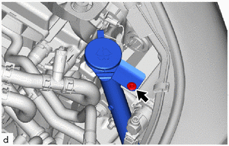
Remove the clip and the neck from the windshield washer jar assembly.
-
Install SST to the vehicle body as shown in the illustration.
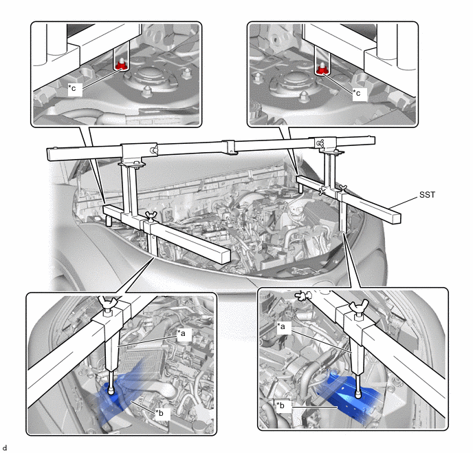
*a Support Shaft *b Front Side Member *c Front Suspension Nut - - - SST
- 09940-10020
CAUTION:
-
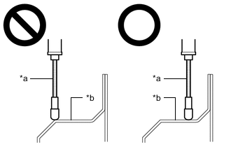
*a Support Shaft *b Front Side Member Make sure that no oil or grease is on the front side member, and set the support shaft on the level surface of the front side member.
-
The engine support bridge may fall off if any oil or grease is still on or it is installed on the unlevel surface.
Note
-
Prevent SST from contacting the vehicle body exterior and windshield glass.
-
To prevent damage to the engine hood, place pieces of cloth between the engine hood and SST.
-
Lightly shake SST by hand to make sure it is securely installed before performing work.
-
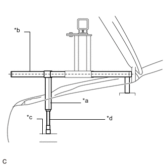
*a Support Shaft *b Sub Beam *c Front Side Member *d Threaded Portion Turn the threaded portion of each support shaft to adjust its height until the sub beams are parallel to the ground.
-
Install the chain block to the sling bracket.
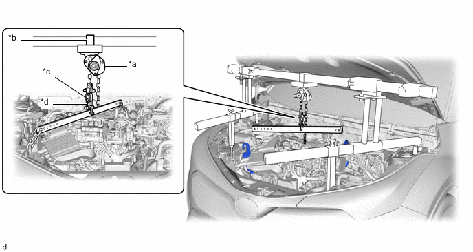
*a Chain Block *b Sling Bracket *c Fuse Shackle *d Shackle (A) -
Install the division bar to the chain block with the shackles.
CAUTION:
-
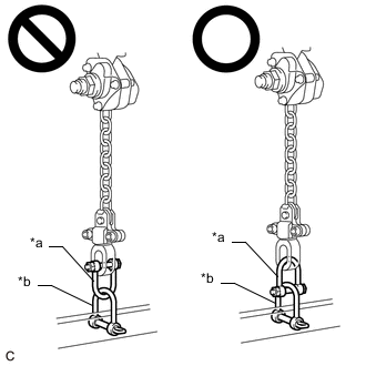
*a Fuse Shackle *b Shackle (A) Make sure the fuse shackle is on the chain block side and the shackle (A) is on the division bar side as shown in the illustration so that the fuse bolt is visible and can be checked for deformation easily.
-
If the fuse shackle is installed upside down, deformation of the fuse bolt will not be visible and cannot be used to tell if the load capacity of the engine support bridge has been exceeded. If the load capacity is exceeded, it may cause the engine support bridge to damage the vehicle and the engine assembly with automatic transaxle assembly may fall.
-
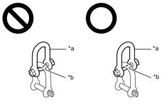
*a Fuse Shackle *b Fuse Bolt Make sure that the fuse bolt of the fuse shackle is free of damage, such as deformation or cracks. If damaged, replace the fuse shackle.
-
If a deformed fuse bolt is used, it cannot be used to tell if the load capacity of the engine support bridge has been exceeded. If the load capacity is exceeded, it may cause the engine support bridge to damage the vehicle and the engine assembly with transaxle assembly may fall.
-
-
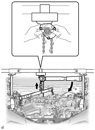
Connect the division bar to the No. 1 engine hanger with the shackle (A) and chain.
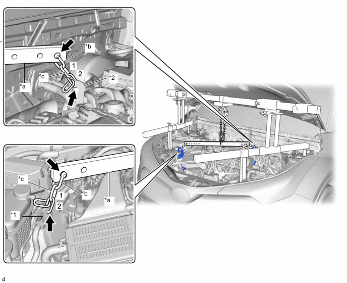
*1 No. 1 Engine Hanger *2 No. 2 Engine Hanger *a Division Bar *b Shackle (A) *c Chain - - -
Connect the division bar to the No. 2 engine hanger with the shackle (A) and chain.
Note
Connect the 2nd link of the chain to the No. 2 engine hanger.
-
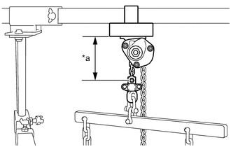
*a 120 mm (4.72 in.) or more Make sure the distance between the chain block assembly and suspension ring is 120 mm (4.72 in.) or more.
Tech Tips
If the suspension height is less than 120 mm, adjust the links of the chain which connect the division bar and engine hanger.
-
Adjust the positions of the chain block assembly, support brackets and main beam so that the chain of the chain block assembly is perpendicular to the main beam and the length of the main beam on the outer side of the support bracket LH and RH is the same as shown in the illustration.
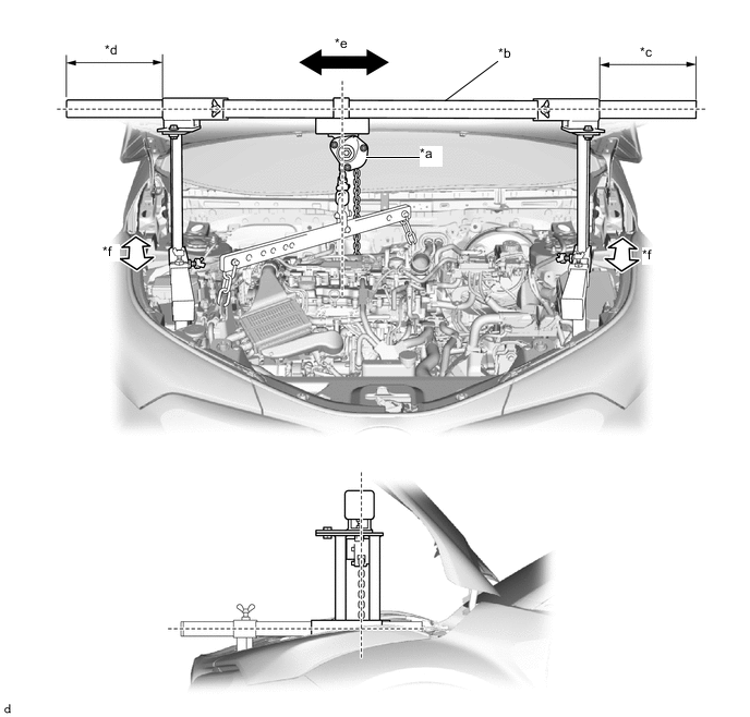
*a Chain Block *b Main Beam *c Dimension (A) *d Dimension (B) *e Right to Left Adjustment *f Front to Rear Adjustment CAUTION:
-
To prevent the engine with automatic transaxle assembly from falling, make sure that the length of dimension (A) and dimension (B) are equal.
-
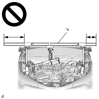
*a Main Beam Do not perform any procedures if the length of dimension (A) and dimension (B) are not equal.
-
Performing any procedure when the length of dimension (A) and dimension (B) are not equal may cause the engine assembly with automatic transaxle assembly and engine support bridge to fall, possibly causing serious injury.
-
-
Confirm the appropriate installation state of the engine support bridge and tighten the 6 wing bolts and 2 bolts.
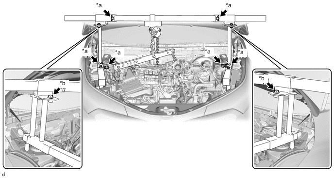
*a Wing Bolt *b Bolt - Torque:
- Bolt
- 30 N*m { 306 kgf*cm, 22 ft.*lbf }
CAUTION:
-
Do not perform any procedures before tightening the bolts to the specified torque.
-
Performing procedures without tightening the bolts to the specified torque, may cause the engine support bridge to fall.
-
*a Turn Tighten the chain block assembly until it cannot be moved any further by hand.
-
-
REMOVE REAR SIDE RAIL REINFORCEMENT SUB-ASSEMBLY LH
-
REMOVE REAR SIDE RAIL REINFORCEMENT SUB-ASSEMBLY RH
-
REMOVE FRONT SUSPENSION CROSSMEMBER SUB-ASSEMBLY
-
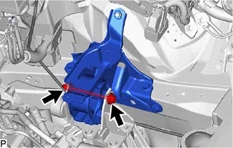
REMOVE NO. 2 ENGINE MOVING CONTROL ROD
-
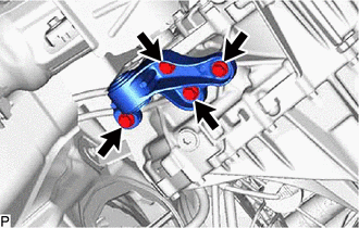
Remove the 4 bolts and No. 2 engine moving control rod from the manual transaxle assembly.
-
-
SUPPORT MANUAL TRANSAXLE ASSEMBLY
-
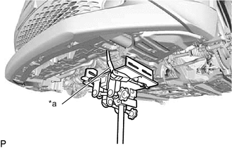
*a Lashing Belt Using a transmission jack, support the manual transaxle assembly.
Note
-
Adjust the attachment of the transmission jack to securely fix the manual transaxle assembly to the transmission jack.
-
Using a lashing belt or a rope, fix the manual transaxle assembly to the transmission jack.
-
-
-
REMOVE STARTER ASSEMBLY (for Cold Area Specification Vehicles)
-
REMOVE STARTER ASSEMBLY (except Cold Area Specification Vehicles)
-
REMOVE FLYWHEEL HOUSING SIDE COVER
-
REMOVE MANUAL TRANSAXLE ASSEMBLY
-
Remove the bolt and nut to separate the transverse engine engine mounting insulator from the engine mounting bracket LH.
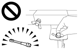
Tech Tips
Turn the bolt while holding the nut.
-
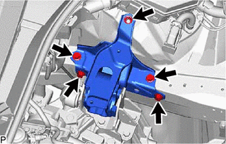
Remove the nut, 4 bolts and transverse engine engine mounting insulator from the vehicle body.
-
Remove the 5 bolts and engine mounting bracket LH from the manual transaxle assembly.
-
*1 Engine Assembly *2 Manual Transaxle Assembly *a Vehicle Body *b Tilt 50 mm (1.97 in.) or less 
Watch for Interference Operate the engine lifter and transmission jack, and slowly tilt the engine assembly with the manual transaxle assembly 50 mm (1.97 in.) or less.
Note
-
Do not allow the engine assembly and manual transaxle assembly to interfere with the vehicle body.
-
Make sure that the engine assembly is not tilted more than necessary.
-
Make sure that the wire harness and hoses are not being pulled.
-
-
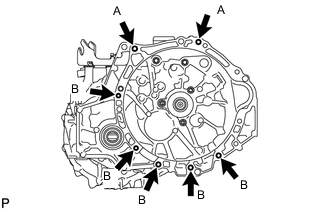
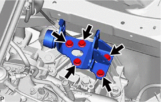
Remove the 7 bolts and engine assembly from the manual transaxle assembly.
Tech Tips
-
Bolt (A): Remove from manual transaxle assembly side.
-
Bolt (B): Remove from engine assembly side.
-
-
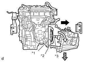
*1 Clutch Disc Assembly *2 Clutch Cover Assembly *3 Input Shaft Using the transmission jack, remove the manual transaxle assembly from the engine assembly according to the procedures shown in the illustration.
Note
-
To prevent damage to the knock pins, do not pry between the manual transaxle assembly and engine assembly.
-
To prevent damage to the input shaft, do not forcefully shake the manual transaxle assembly.
-
Make sure the manual transaxle assembly does not interfere with the clutch tube or other components.
-
Move the manual transaxle assembly towards the left side of the vehicle and disengage the input shaft from the clutch disc assembly.
-
Tilt the manual transaxle assembly and pull the input shaft out from the clutch cover assembly.
-
Lower the manual transaxle assembly.
-
-
-
REMOVE BLEEDER CLUTCH RELEASE TUBE
-
REMOVE CLUTCH FLEXIBLE HOSE BRACKET
-
Remove the bolt and clutch flexible hose bracket from the manual transaxle assembly.
-
-
REMOVE CLUTCH RELEASE BLEEDER SUB-ASSEMBLY
-
REMOVE CLUTCH RELEASE CYLINDER WITH BEARING ASSEMBLY
-
REMOVE WIRE HARNESS CLAMP BRACKET
-
Remove the bolt and wire harness clamp bracket from the manual transmission case.
-
-
REMOVE NO. 1 HEATER BRACKET SUB-ASSEMBLY
-
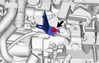
Remove the bolt and No. 1 heater bracket sub-assembly from the manual transmission case.
-
-
REMOVE CONTROL CABLE BRACKET ASSEMBLY
-
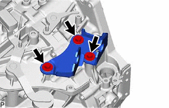
Remove the 3 bolts and control cable bracket assembly from the manual transmission case.
-
-
REMOVE SPEEDOMETER DRIVEN HOLE COVER SUB-ASSEMBLY
-
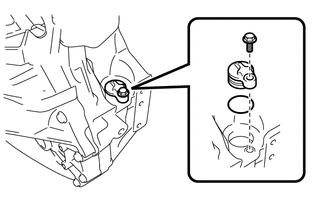
Remove the bolt and speedometer driven hole cover sub-assembly from the manual transaxle assembly.
-
Remove the O-ring from the speedometer driven hole cover sub-assembly.
-