CAMSHAFT REMOVAL
CAUTION / NOTICE / HINT
The necessary procedures (adjustment, calibration, initialization, or registration) that must be performed after parts are removed, installed, or replaced during the camshaft removal/installation are shown below.
| Replacement Part or Procedure | Necessary Procedure | Effect/Inoperative when not Performed | Link |
|---|---|---|---|
| Disconnect cable from negative battery terminal | Drive the vehicle until stop and start control is permitted (approximately 5 to 60 minutes) | Stop and start system | |
| Memorize steering angle neutral point | LKA/LDA system | ||
| Parking support brake system*1 | |||
| Pre-collision system | |||
| Adaptive high beam system | |||
Lighting system (EXT) |
|||
| Variable gear ratio steering system | |||
| Parking assist monitor system | |||
| Panoramic view monitor system | |||
| Initialize rear door sunshade system | Rear door sunshade system | ||
| Initialize power trunk lid system | Power trunk lid system | ||
|
Inspection after repair |
|
Click here Click here
PROCEDURE
-
DRAIN ENGINE COOLANT
-
PRECAUTION
Note
After turning the engine switch off, waiting time may be required before disconnecting the cable from the battery terminal. Therefore, make sure to read the disconnecting the cable from the battery terminal notice before proceeding with work.
-
REMOVE LUGGAGE COMPARTMENT MAT SUB-ASSEMBLY
-
DISCONNECT CABLE FROM NEGATIVE BATTERY TERMINAL
Note
When disconnecting the cable, some systems need to be initialized after the cable is reconnected.
-
REMOVE INTAKE AIR SURGE TANK ASSEMBLY
-
REMOVE VACUUM PUMP ASSEMBLY
-
REMOVE FUEL PUMP ASSEMBLY (for High Pressure)
-
DISCONNECT NO. 1 RADIATOR HOSE
-
DISCONNECT NO. 3 RADIATOR HOSE
-
DISCONNECT ENGINE WIRE
-
DISCONNECT NO. 3 ENGINE WIRE
-
REMOVE IGNITION COIL ASSEMBLY
-
REMOVE SPARK PLUG
-
REMOVE NO. 2 ENGINE OIL LEVEL DIPSTICK GUIDE
-
REMOVE CAMSHAFT TIMING OIL CONTROL SOLENOID ASSEMBLY (for Intake Side of Bank 1)
-
REMOVE CAMSHAFT TIMING OIL CONTROL SOLENOID ASSEMBLY (for Exhaust Side of Bank 1)
-
REMOVE CAMSHAFT TIMING OIL CONTROL SOLENOID ASSEMBLY (for Intake Side of Bank 2)
-
REMOVE CAMSHAFT TIMING OIL CONTROL SOLENOID ASSEMBLY (for Exhaust Side of Bank 2)
-
REMOVE VVT SENSOR (for Intake Side of Bank 1)
-
REMOVE VVT SENSOR (for Exhaust Side of Bank 1)
-
REMOVE VVT SENSOR (for Intake Side of Bank 2)
-
REMOVE VVT SENSOR (for Exhaust Side of Bank 2)
-
REMOVE NO. 1 ENGINE COVER SUB-ASSEMBLY
-
REMOVE NO. 1 FUEL TUBE SUB-ASSEMBLY
-
REMOVE CYLINDER HEAD COVER SUB-ASSEMBLY LH
-
REMOVE CYLINDER HEAD COVER SUB-ASSEMBLY
-
REMOVE SPARK PLUG TUBE GASKET
-
REMOVE TIMING CHAIN COVER PLATE
-
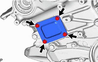
Remove the 4 bolts, timing chain cover plate and gasket.
-
-
SET NO. 1 CYLINDER TO TDC/COMPRESSION
-

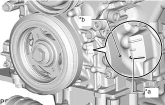
*a "0" Timing Mark *b Timing Mark (Cutout) Turn the crankshaft clockwise to align the timing mark (cutout) on the crankshaft pulley assembly with the "0" timing mark on the timing chain cover assembly.
-
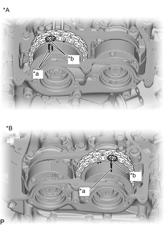
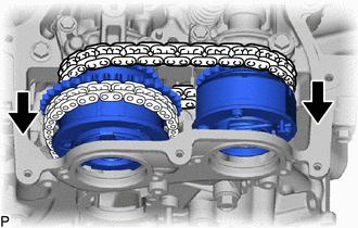
*A for Bank 2 *B for Bank 1 *a Paint Mark *b Timing Mark Check that the timing marks of the camshaft timing gears are aligned with the timing marks of the bearing caps as shown in the illustration.
Tech Tips
If the marks are not aligned, turn the crankshaft again to align the marks.
-
Place paint marks on the timing marks and sprockets of each camshaft timing gear and on the links of the chain.
Tech Tips
Be sure to place the paint marks on 2 links of the chain sub-assembly and on the sprockets of the camshaft timing gears at the locations of the timing marks of the camshaft timing gears.
-
-
REMOVE NO. 1 CHAIN TENSIONER ASSEMBLY
-
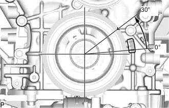
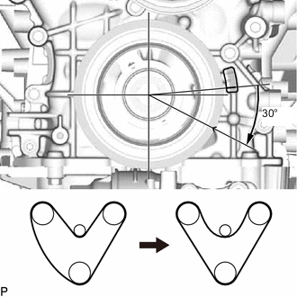
Turn the crankshaft approximately 30° counterclockwise so that there is some slack in the chain.
Tech Tips
This prevents the valves and pistons from interfering with each other.
-
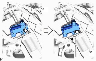
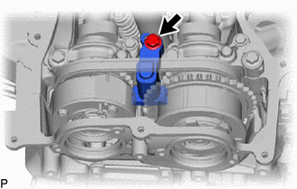
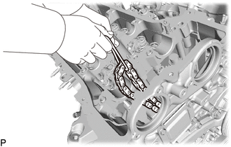
*a Lever Hole *b Tensioner Hole *c Pin Align the hole in the lever of the No. 1 chain tensioner assembly with the hole in the tensioner body as shown in the illustration, and then insert a pin with a diameter of 1.27 mm (0.0500 in.) into the hole.
-
*a "0" Timing Mark *b Timing Mark (Cutout) Turn the crankshaft clockwise to align the timing mark (cutout) on the crankshaft pulley assembly with the "0" timing mark on the timing chain cover assembly.
-
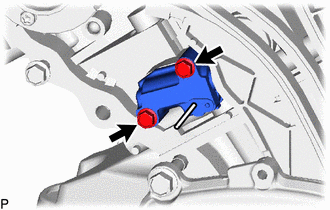
Remove the 2 bolts and No. 1 chain tensioner assembly.
Note
Do not drop the No. 1 chain tensioner assembly or bolts into the timing chain cover assembly.
-
-
DISCONNECT CHAIN SUB-ASSEMBLY (for Bank 1)
-
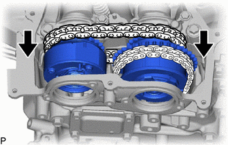
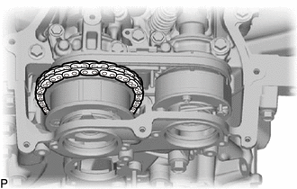
Turn the crankshaft clockwise until it is in the position shown in the illustration so that there is some slack in the chain sub-assembly between the banks.
CAUTION:
As the camshafts turn suddenly, do not touch the camshafts or camshaft timing gears.
Tech Tips
When turning the crankshaft, engine oil may spray out of the oil holes.
-
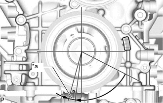
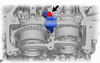
*a 5° to 10° Turn the crankshaft clockwise until it is in the position shown in the illustration so that the chain can be removed easily.
Note
When turning the crankshaft, engine oil may spray out of the oil holes.
-
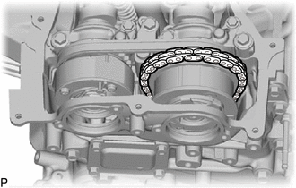
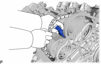
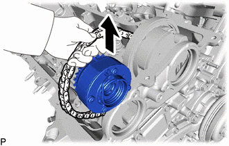
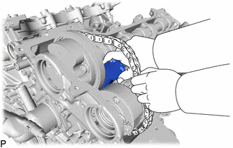
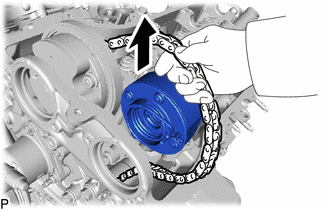
Remove the chain sub-assembly from the sprocket of the camshaft timing gear and set it on the gear.
CAUTION:
As the camshaft may turn suddenly and pinch your fingers when the chain sub-assembly is removed, pinch the chain sub-assembly and lift it upward to remove it from the sprocket.
-
-
REMOVE NO. 2 CHAIN TENSIONER ASSEMBLY
-
Remove the bolt of the No. 2 chain tensioner assembly.
-
-
REMOVE CAMSHAFT TIMING GEAR BOLT (for Intake Side of Bank 1)
-
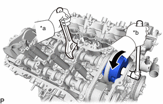
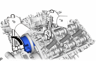
*a Hold *b Turn Hold the hexagonal portion of the camshaft with a wrench and remove the camshaft timing gear bolt from the camshaft timing gear assembly.
Note
Be careful not to damage the camshaft or cylinder head sub-assembly with the wrench.
-
-
REMOVE CAMSHAFT TIMING GEAR (for Exhaust Side of Bank 1)
-
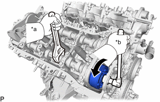
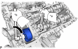
*a Hold *b Turn Hold the hexagonal portion of the No. 2 camshaft with a wrench and remove the camshaft timing gear bolt from the camshaft timing exhaust gear assembly RH.
Note
Be careful not to damage the camshaft or cylinder head sub-assembly with the wrench.
-
-
REMOVE CAMSHAFT BEARING CAP (for Bank 1)
-
Slide the camshaft timing gear assembly and camshaft timing exhaust gear assembly toward the front of the vehicle.
-
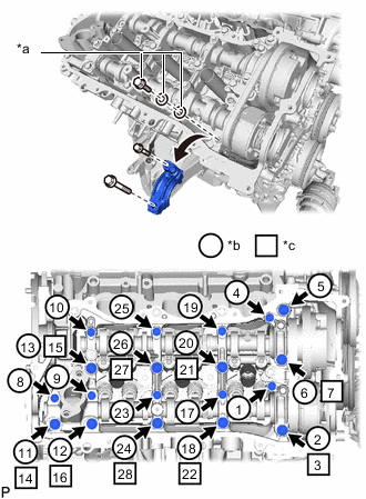
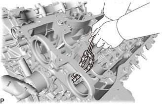
*a Replacement Bolt and Washer *b Part Removal *c Replacement Bolt and Washer Installation Remove the bolts and bearing caps in the order shown in the illustration. Immediately after removing a bearing cap, install replacement bolts and washers in the order shown in the illustration.
- Torque:
- 10 N*m { 102 kgf*cm, 7 ft.*lbf }
Note
-
Do not install the bearing caps when installing replacement bolts and washers.
-
Be sure to follow the numerical order when performing this procedure.
-
Do not allow replacement bolts or washers to contact the camshaft.
-
Do not drop replacement bolts or washers into the cylinder head sub-assembly.
Tech Tips
-
Arrange the removed parts so that they can be reinstalled in their original locations.
-
Part number for replacement bolts: 91551-F0850 (9 bolts)
-
Part number for replacement washers: 90201-12028 (18 washers)
-
-
REMOVE NO. 2 CAMSHAFT
-
Remove the No. 2 chain tensioner assembly.
-
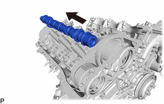
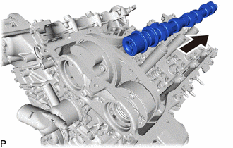
Lift up the rear of the No. 2 camshaft so that it is at an angle.
-
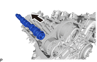
Pull the No. 2 camshaft toward the rear of the vehicle to remove it from the camshaft timing exhaust gear assembly.
-
-
REMOVE CAMSHAFT
-
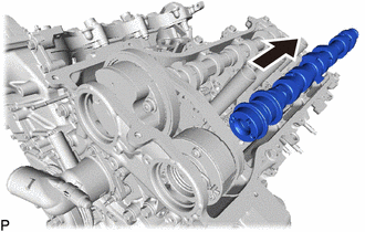
Lift up the rear of the camshaft so that it is at an angle.
-
Pull the camshaft toward the rear of the vehicle to remove it from the camshaft timing gear assembly.
-
-
REMOVE CAMSHAFT TIMING EXHAUST GEAR ASSEMBLY (for Bank 1)
-
Remove the camshaft timing exhaust gear assembly and No. 2 chain sub-assembly.
-
-
REMOVE CAMSHAFT TIMING GEAR ASSEMBLY (for Bank 1)
-
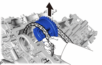
Remove the camshaft timing gear assembly.
Note
Do not drop the chain sub-assembly into the gap between the engine and cover.
-
Suspend the chain sub-assembly with a string or equivalent.
-
-
DISCONNECT CHAIN SUB-ASSEMBLY (for Bank 2)
-
*a "0" Timing Mark *b Timing Mark (Cutout) Turn the crankshaft clockwise to align the timing mark (cutout) on the crankshaft pulley assembly with the "0" timing mark on the timing chain cover assembly.
-
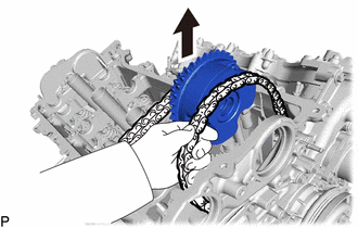
Remove the chain sub-assembly from the sprocket of the camshaft timing gear and set it on the gear.
Note
As the camshaft may turn suddenly and pinch your fingers when the chain sub-assembly is removed, pinch the chain sub-assembly and lift it upward to remove it from the sprocket.
-
-
REMOVE NO. 3 CHAIN TENSIONER ASSEMBLY
-
Remove the bolt of the No. 3 chain tensioner assembly.
-
-
REMOVE CAMSHAFT TIMING GEAR BOLT (for Intake Side of Bank 2)
-
*a Hold *b Turn Hold the hexagonal portion of the No. 3 camshaft with a wrench and remove the camshaft timing gear bolt from the camshaft timing gear assembly LH.
Note
Be careful not to damage the camshaft or cylinder head sub-assembly with the wrench.
-
-
REMOVE CAMSHAFT TIMING GEAR BOLT (for Exhaust Side of Bank 2)
-
*a Hold *b Turn Hold the hexagonal portion of the No. 4 camshaft sub-assembly with a wrench and remove the camshaft timing gear bolt from the camshaft timing exhaust gear assembly LH.
Note
Be careful not to damage the camshaft or cylinder head sub-assembly with the wrench.
-
-
REMOVE CAMSHAFT BEARING CAP (for Bank 2)
-
Slide the camshaft timing gear assembly and camshaft timing exhaust gear assembly toward the front of the vehicle.
-
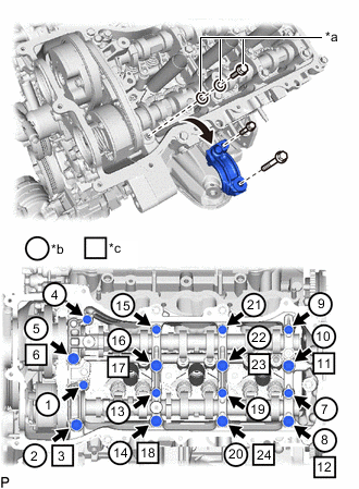
*a Replacement Bolt and Washer *b Part Removal *c Replacement Bolt and Washer Installation Remove the bolts and bearing caps in the order shown in the illustration. Immediately after removing a bearing cap, install replacement bolts and washers in the order shown in the illustration.
- Torque:
- 10 N*m { 102 kgf*cm, 7 ft.*lbf }
Note
-
Do not install the bearing caps when installing replacement bolts and washers.
-
Be sure to follow the numerical order when performing this procedure.
-
Do not allow replacement bolts or washers to contact the camshaft.
-
Do not drop replacement bolts or washers into the cylinder head sub-assembly.
Tech Tips
-
Arrange the removed parts so that they can be reinstalled in their original locations.
-
Part number for replacement bolts: 91551-F0850 (8 bolts)
-
Part number for replacement washers: 90201-12028 (16 washers)
-
-
REMOVE NO.4 CAMSHAFT SUB-ASSEMBLY
-
Remove the No. 3 chain tensioner assembly.
-
Lift up the rear of the No. 4 camshaft sub-assembly so that it is at an angle.
-
Pull the No. 4 camshaft sub-assembly toward the rear of the vehicle to remove it from the camshaft timing exhaust gear assembly.
-
-
REMOVE NO.3 CAMSHAFT SUB-ASSEMBLY
-
Lift up the rear of the camshaft so that it is at an angle.
-
Pull the No. 3 camshaft sub-assembly toward the rear of the vehicle to remove it from the camshaft timing gear assembly.
-
-
REMOVE CAMSHAFT TIMING EXHAUST GEAR ASSEMBLY (for Bank 2)
-
Remove the camshaft timing exhaust gear assembly and No. 2 chain sub-assembly.
-
-
REMOVE CAMSHAFT TIMING GEAR ASSEMBLY (for Bank 2)
-
Remove the camshaft timing gear assembly.
Note
Do not drop the chain sub-assembly into the gap between the engine and timing chain cover assembly.
-
Suspend the chain sub-assembly with a string or equivalent.
-