BRAKE PEDAL(for RHD with Vacuum Brake Booster) REMOVAL
CAUTION / NOTICE / HINT
The necessary procedures (adjustment, calibration, initialization, or registration) that must be performed after parts are removed, installed, or replaced during brake pedal support assembly removal/installation are shown below.
| Replaced Part or Performed Procedure | Necessary Procedure | Effect/Inoperative Function when Necessary Procedure not Performed | Link |
|---|---|---|---|
| Battery terminal is disconnected/reconnected | Drive the vehicle until stop and start control is permitted (approximately 5 to 60 minutes) | Stop and start system | for 8GR-FKS: Click here for V35A-FTS: Click here |
| Memorize steering angle neutral point | LKA/LDA system | ||
| Parking support brake system* | |||
| Pre-collision system | |||
| Adaptive high beam system | |||
Lighting system (EXT) |
|||
| Variable gear ratio steering system | |||
| Parking assist monitor system | |||
| Panoramic view monitor system | |||
| Initialize rear door sunshade system | Rear door sunshade system | ||
| Initialize power trunk lid system | Power trunk lid system | ||
Electronically Controlled Brake System (w/o Vacuum Brake Booster): |
|
|
Click here Click here
PROCEDURE
-
PRECAUTION
Note
After turning the engine switch off, waiting time may be required before disconnecting the cable from the negative (-) battery terminal. Therefore, make sure to read the disconnecting the cable from the negative (-) battery terminal notices before proceeding with work.
-
REMOVE STEERING COLUMN ASSEMBLY
-
DISCONNECT BRAKE PEDAL SUPPORT ASSEMBLY
-
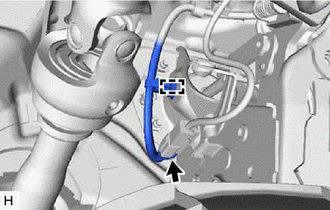
Disconnect the brake pedal load sensing switch connector.
-
Disconnect the wire harness clamp from the brake pedal support assembly.
-
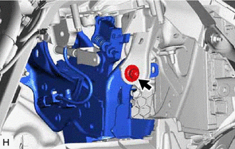
Remove the bolt and separate the brake pedal support assembly from the instrument panel reinforcement assembly.
-
-
REMOVE INSTRUMENT PANEL REINFORCEMENT ASSEMBLY
-
REMOVE BRAKE PEDAL RETURN SPRING
-
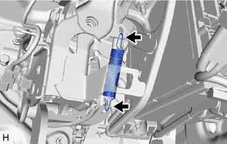
Remove the brake pedal return spring from the brake pedal support assembly.
-
-
REMOVE STOP LIGHT SWITCH ASSEMBLY
-
REMOVE STOP LIGHT SWITCH MOUNTING ADJUSTER
-
REMOVE PUSH ROD PIN
-
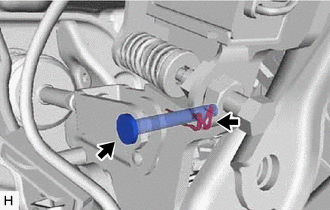
Remove the clip and push rod pin.
-
-
REMOVE BRAKE PEDAL SUPPORT ASSEMBLY
-
Remove the 2 clips from brake pedal support assembly.
-
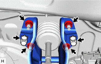
Remove the 4 nuts and brake pedal support assembly.
-
-
REMOVE BRAKE PEDAL PAD
-
Remove the brake pedal pad from the brake pedal support assembly.
-