CYLINDER BLOCK DISASSEMBLY
CAUTION / NOTICE / HINT
The necessary procedures (adjustment, calibration, initialization, or registration) that must be performed after parts are removed, installed, or replaced during the cylinder block removal/installation are shown below.
| Replaced Part or Performed Procedure | Necessary Procedure | Effect/Inoperative Function when Necessary Procedure not Performed | Link |
|---|---|---|---|
| Battery terminal is disconnected/reconnected | Drive the vehicle until stop and start control is permitted (approximately 5 to 60 minutes) | Stop and start system | |
| Memorize steering angle neutral point | LKA/LDA system | ||
| Parking support brake system* | |||
| Pre-collision system | |||
| Adaptive high beam system | |||
Lighting system (EXT) |
|||
| Variable gear ratio steering system | |||
| Parking assist monitor system | |||
| Panoramic view monitor system | |||
| Initialize rear door sunshade system | Rear door sunshade system | ||
| Initialize power trunk lid system | Power trunk lid system | ||
|
Inspection after repairs |
|
w/ Canister Pump Module: w/o Canister Pump Module: |
| Piston ring | Inspection after repair |
|
|
Heavy Knock History |
- | ||
| Replacement of engine assembly | Inspection after repair |
|
w/ Canister Pump Module: w/o Canister Pump Module: |
|
|
for AGA0E: for AGA0F: |
|
| ECM | Vehicle Identification Number (VIN) registration | DTC P063051 is output | w/ Canister Pump Module: w/o Canister Pump Module: |
Heavy Knock History |
- | ||
| Parts between the steering wheel and tires have been removed/installed, replaced or adjusted | Perform Actuator Angle Neutral Point Calibration and Initialization |
|
|
| Front bumper assembly (Including removal and installation) |
|
Parking support brake system | |
| Front television camera view adjustment | Panoramic view monitor system | ||
| Suspension, tires, etc |
|
Parking support brake system | |
|
Panoramic view monitor system | ||
| Rear television camera assembly optical axis (Back camera position setting) | Parking assist monitor system |
Click here Click here
Note
This procedure includes the removal of small-head bolts. Refer to Small-Head Bolts of Basic Repair Hint to identify the small-head bolts.
PROCEDURE
-
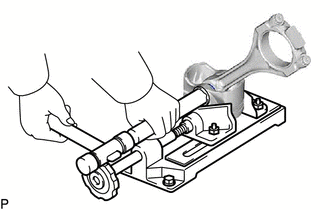
INSPECT CONNECTING ROD THRUST CLEARANCE
-
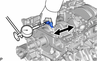
Using a dial indicator, measure the thrust clearance while moving the connecting rod back and forth.
Standard thrust clearance 0.15 to 0.40 mm (0.00591 to 0.0157 in.) Maximum thrust clearance 0.50 mm (0.0197 in.) Tech Tips
If the thrust clearance is more than the maximum, replace the connecting rod sub-assembly. If necessary, replace the crankshaft.
-
-
INSPECT CONNECTING ROD OIL CLEARANCE
-
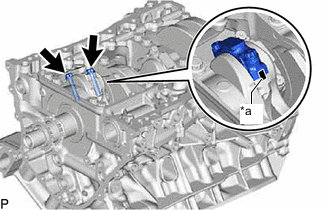
*a Matchmarks Check that the matchmarks on the connecting rod sub-assembly and connecting rod cap are aligned.
Tech Tips
The matchmarks on the connecting rod sub-assembly and connecting rod cap are guides for correct reassembly.
-
Remove the 2 connecting rod cap bolts.
-
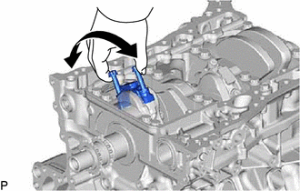
Using the 2 removed connecting rod cap bolts, remove the connecting rod cap and lower bearing by wiggling the connecting rod cap right and left.
Tech Tips
Keep the lower bearing inserted to the connecting rod cap.
-
Clean the crank pin and bearing.
-
Check the crank pin and bearing for pitting and scratches.
-
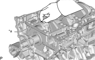
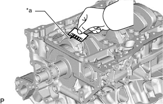
*a Plastigage Lay a strip of Plastigage on the crank pin.
-
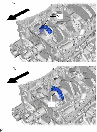
*a for Bank 1 (Piston RH) *b for Bank 2 (Piston LH) *c Piston Matchmark (Protrusion) 
Engine Front Check that the piston matchmark (protrusion) of the connecting rod cap is facing forward.
Note
-
Take care as the piston matchmark (protrusion) on the piston RH connecting rod is reversed for the piston LH.
-
The match on the connecting rod sub-assembly and connecting rod cap are guides for correct reassembly.
-
-
Install the connecting rod cap.
Note
Do not turn the crankshaft.
-
Remove the 2 bolts and connecting rod cap.
-
*a Plastigage Measure the Plastigage at its widest point.
Standard oil clearance 0.047 to 0.075 mm (0.00185 to 0.00295 in.) Maximum oil clearance 0.080 mm (0.00315 in.) If the oil clearance is more than the maximum, replace the connecting rod bearings. If necessary, inspect the crankshaft.
Standard Connecting Rod Diameter Mark Specified Condition 1 58.400 to 58.406 mm (2.29920 to 2.29944 in.) 2 58.407 to 58.412 mm (2.29948 to 2.29968 in.) 3 58.413 to 58.418 mm (2.29971 to 2.29991 in.) 4 58.419 to 58.424 mm (2.29991 to 2.30015 in.) Standard Connecting Rod Bearing Center Wall Thickness Mark Specified Condition 1 1.482 to 1.485 mm (0.05835 to 0.05846 in.) 2 1.486 to 1.488 mm (0.05850 to 0.05858 in.) 3 1.489 to 1.491 mm (0.05862 to 0.05870 in.) 4 1.492 to 1.494 mm (0.05874 to 0.05882 in.) Standard crankshaft pin diameter 55.392 to 55.400 mm (2.1808 to 2.1810 in.) Note
Completely remove the Plastigage after the measurement.
-
-
REMOVE PISTON SUB-ASSEMBLY WITH CONNECTING ROD
-
Using a ridge reamer, remove all the carbon from the top of the cylinder.
-
Push the piston, connecting rod assembly and upper bearing through the top of the cylinder block sub-assembly.
Tech Tips
-
Keep the bearing, connecting rod and cap together.
-
Arrange the piston and connecting rod assemblies in the correct order.
-
-
-
REMOVE CONNECTING ROD BEARING
-
Remove the connecting rod bearings from the connecting rods and connecting rod caps.
Tech Tips
Arrange the removed parts in the correct order.
-
-
REMOVE CRANKSHAFT
-
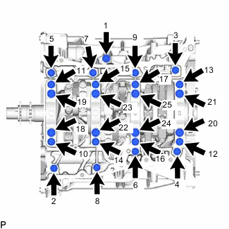
Uniformly loosen the 16 crankshaft bearing cap bolts in several steps and in the sequence shown in the illustration.
-
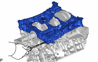
*a Protective Tape Using a screwdriver, pry out the crankshaft bearing cap sub-assembly.
Note
-
Push up on the cap slowly and evenly, alternating from the right and left side so that the crankshaft bearing cap sub-assembly can be removed.
-
Be careful not to damage the joint surfaces of the cylinder block and the crankshaft bearing cap sub-assembly.
Tech Tips
Tape the screwdriver tip before use.
-
-
Remove the crankshaft from the cylinder block sub-assembly.
-
Remove the gasket from the crankshaft bearing cap sub-assembly.
-
-
REMOVE CRANKSHAFT BEARING
-
Remove the crankshaft bearings from the cylinder block sub-assembly and crankshaft bearing cap sub-assembly.
Tech Tips
Arrange the removed parts in the correct order.
-
-
REMOVE CRANKSHAFT THRUST WASHER SET
-
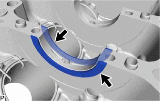
Remove the crankshaft thrust washers from the cylinder block sub-assembly.
-
-
REMOVE PISTON RING SET
-
*a Piston Ring Expander Using a piston ring expander, remove the 2 compression rings.
-
Remove the oil ring expander and 2 side rails by hand.
Tech Tips
Arrange the removed parts in the correct order.
-
-
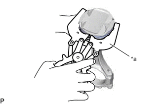
REMOVE PISTON SUB-ASSEMBLY WITH PIN
-
Disconnect the connecting rod from the piston.
-
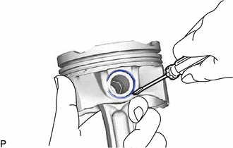
Using a screwdriver, pry off the piston pin hole snap rings from the piston.
-
Gradually heat the piston to approximately 80°C (176°F).
-
Using a brass bar and a plastic-faced hammer, lightly tap out the piston pin and remove the connecting rod sub-assembly.
Tech Tips
-
The piston and piston pin are a matched set.
-
Arrange the pistons, piston pins, connecting rods and connecting rod bearings in the correct order.
-
-
-
Using a gasket scraper, remove the carbon from the piston top.
-
Using a groove cleaning tool or broken ring, clean the piston ring grooves.
-
Using solvent and a brush, thoroughly clean the piston.
Note
Do not use a wire brush.
-
-
REMOVE NO. 1 OIL NOZZLE SUB-ASSEMBLY
-
Using a 5 mm hexagon wrench, remove the 6 bolts and No. 1 oil nozzle sub-assemblies.
-
Check the 6 No. 1 oil nozzle sub-assemblies for damage or clogging.
If necessary, replace the No. 1 oil nozzle sub-assembly.
-
-
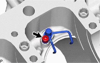
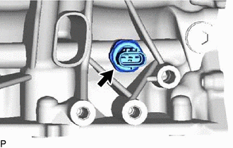
REMOVE OIL PRESSURE SWITCHING VALVE ASSEMBLY (w/ GPF)
-
Remove the bolt and oil pressure switching valve assembly from the cylinder block insert spacer.
-
-
REMOVE CYLINDER BLOCK INSERT SPACER
-
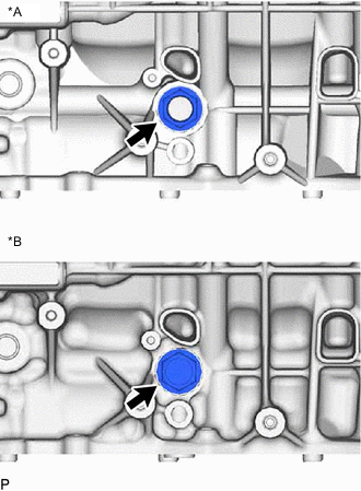
*A w/ GPF *B w/o GPF Remove the cylinder block insert spacer and gasket from the cylinder block sub-assembly.
-
-
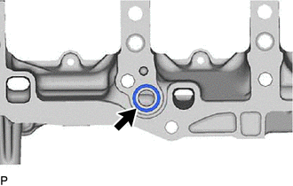
REMOVE CYLINDER BLOCK PLUG WITH HEAD STRAIGHT SCREW
-
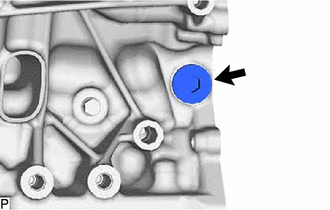
Using a 10 mm hexagon socket, remove the cylinder block plug with head straight screw and gasket from the cylinder block sub-assembly.
-
-
REMOVE NO. 1 PLUG WITH HEAD TAPER SCREW
-
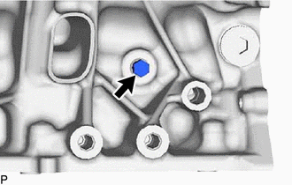
Remove the No. 1 plug with head taper screw from the cylinder block sub-assembly.
-
-
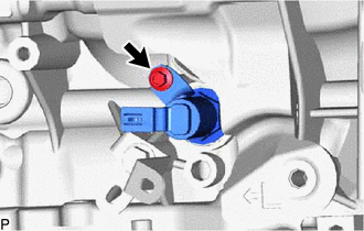
REMOVE OIL PRESSURE SENDER GAUGE ASSEMBLY (w/ GPF)
-
Using a 27 mm deep socket wrench, remove the oil pressure sender gauge assembly.
-