DIFFERENTIAL OIL SEAL(for RH Side) REPLACEMENT

CAUTION / NOTICE / HINT
The necessary procedures (adjustment, calibration, initialization or registration) that must be performed after parts are removed and installed, or replaced during transaxle case oil seal and front drive shaft oil seal RH removal/installation are shown below.
| Replaced Part or Performed Procedure | Necessary Procedure | Effect/Inoperative Function when Necessary Procedure not Performed | Link |
|---|---|---|---|
| Battery terminal is disconnected/reconnected | Memorize steering angle neutral point | LKA/LDA System | |
| Pre-crash safety system | |||
| Lighting system (EXT)
|
|||
| Adaptive high beam system | |||
| Drive the vehicle until stop and start control is permitted (approximately 15 to 60 minutes) | Stop and start system | ||
| Memorize steering angle neutral point | Parking Assist Monitor System (w/ Parallel Parking Assist Function) | ||
| Parking Assist Monitor System (w/o Parallel Parking Assist Function) | |||
| Panoramic view monitor system | |||
| Initialize back door lock | Power door lock control system | ||
| Reset back door close position | Power back door system | ||
| Replacement of automatic transaxle assembly | Perform the following procedures in the order shown:
|
|
for Initialization: for Registration: |
| Replacement of ECM (If possible, read the transaxle compensation code from the previous ECM) |
Perform the following procedures in the order shown:
|
||
| Replacement of ECM (If impossible, read the transaxle compensation code from the previous ECM) |
Perform the following procedures in the order shown:
|
||
| Replacement of engine assembly | Perform the following procedures in the order shown:
|
||
| Front wheel alignment adjustment |
|
|
|
| Suspension, tires, etc. (The vehicle height changes because of suspension or tire replacement) |
Rear television camera assembly optical axis (Back camera position setting) | Parking assist monitor system (w/ Parallel Parking Assist Function) | for Initialization: for Calibration: |
| Parking assist monitor system (w/o Parallel Parking Assist Function) | for Initialization: for Calibration: |
||
|
Panoramic view monitor system | for Initialization: for Calibration: |
|
| Initialize headlight ECU sub-assembly LH |
|
||
| Replacement of engine assembly | Inspection After Repair |
|
w/ Canister Pump Module: w/o Canister Pump Mod: |
| Air leaks from intake system is repaired | |||
| Gas leak from exhaust system is repaired | |||
| Replacement of ECM | Perform Vehicle Identification Number (VIN) or frame number registration |
|
w/ Canister Pump Module: w/o Canister Pump Mod: |
| ECU Communication ID Registration (Immobiliser system) | Engine start function | See Service Bulletin for the registration method. | |
| Perform code registration (Immobiliser system) |
|
CAUTION:
-
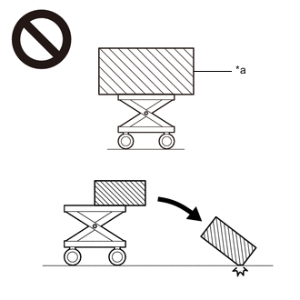
*a Object Exceeding Weight Limit of Engine Lifter The engine assembly with transaxle is very heavy. Be sure to follow the procedure described in the repair manual, or the engine lifter may suddenly drop or the engine assembly with transaxle may fall off the engine lifter.
-
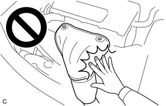
To prevent burns, do not touch the engine, exhaust manifold or other high temperature components while the engine is hot.
-
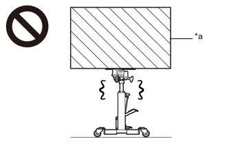
*a Object Exceeding Weight Limit of Transmission Jack The automatic transaxle assembly is very heavy. Be sure to follow the procedure described in the repair manual, or the transmission jack may suddenly drop.
Note
If automatic transaxle parts are replaced, refer to Parts Replacement Compensation Table to determine if any additional operations are necessary.
PROCEDURE
-
PRECAUTION
Note
If automatic transaxle assembly parts are replaced, refer to Parts Replacement Compensation Table to determine if any additional operations are necessary.
-
REMOVE TRANSFER ASSEMBLY
-
REMOVE TRANSAXLE CASE OIL SEAL
-
*a Protective Tape Using a screwdriver with its tip wrapped with protective tape, remove the transaxle case oil seal from the transaxle housing.
Note
Be careful not to damage the front differential case or transaxle housing.
-
-
REMOVE FRONT DRIVE SHAFT OIL SEAL RH
-
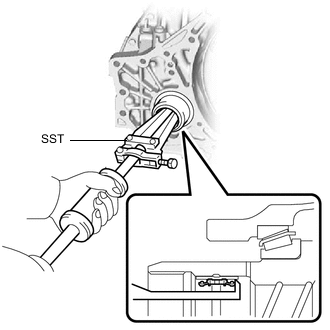
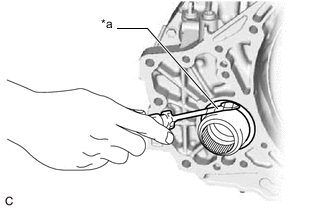
Using SST, remove the front drive shaft oil seal RH from the front differential case.
- SST
- 09308-00010
Note
Be careful not to damage the front differential case.
-
-
INSTALL FRONT DRIVE SHAFT OIL SEAL RH
-
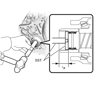
*a Depth Coat the lip of a new front drive shaft oil seal RH with MP grease.
-
Using SST and a hammer, install the front drive shaft oil seal RH to the front differential case.
- SST
- 09950-60010 ( 09951-00410 )
- 09950-70010 ( 09951-07200 )
Standard Depth 21.5 to 22.5 mm (0.846 to 0.886 in.) Note
Do not damage the lip of the front drive shaft oil seal RH.
-
-
INSTALL TRANSAXLE CASE OIL SEAL
-
Coat the lip of a new transaxle case oil seal with MP grease.
-
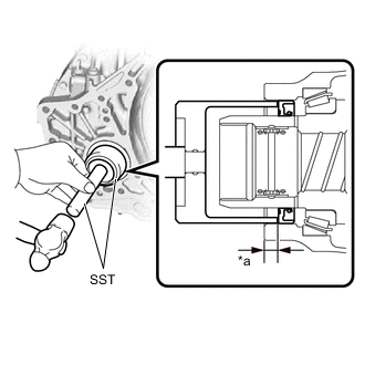
*a Depth Using SST and a hammer, install the transaxle case oil seal to the transaxle housing.
- SST
- 09649-17010
- 09950-70010 ( 09951-07200 )
Standard Depth 5.5 to 6.5 mm (0.217 to 0.256 in.) Note
-
Make sure that the transaxle case oil seal is installed in the correct direction.
-
Do not damage the lip of the transaxle case oil seal.
-
-
INSTALL TRANSFER ASSEMBLY