ENGINE ASSEMBLY REMOVAL

CAUTION / NOTICE / HINT
The necessary procedures (adjustment, calibration, initialization, or registration) that must be performed after parts are removed, installed, or replaced during the engine assembly removal/installation are shown below.
| Replacement Part or Procedure | Necessary Procedures | Effects/Inoperative when not Performed | Link |
|---|---|---|---|
| Replacement of ECM |
|
Engine starting | |
| Code registration (Immobiliser system) | Engine start function | See the Service Bulletin for the registration method. | |
| Replacement of engine assembly |
|
Engine starting | |
| Clear Crank Time Compensation Data | Engine starting | ||
| Replacement of crankshaft position sensor plate | Clear Crank Time Compensation Data | Crank time compensation data compensation amount is same as before replacement, affecting crank time compensation data | |
| Replacement of injector assembly |
|
Engine starting | |
|
Perform initialization | - | |
for AC60F: |
Reset memory |
|
|
for AC60F: |
ATF thermal degradation estimate reset | The value of the Data List item "ATF Thermal Degradation Estimate" is not estimated correctly | |
w/ Automatic Headlight Beam Level Control System: |
Headlight leveling ECU assembly initialization | Headlight leveling function | |
for 4WD: |
|
VSC malfunctioning |
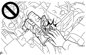
CAUTION:
To prevent burns, do not touch the engine, exhaust manifold or other high temperature components while the engine is hot.
PROCEDURE
-
PRECAUTION
Note
After turning the ignition switch off, waiting time may be required before disconnecting the cable from the battery terminal. Therefore, make sure to read the disconnecting the cable from the battery terminal notice before proceeding with work.
-
DISCONNECT CABLE FROM NEGATIVE BATTERY TERMINAL
Note
When disconnecting the cable, some systems need to be initialized after the cable is reconnected.
-
REMOVE NO. 1 ENGINE UNDER COVER ASSEMBLY (for 4WD and Pre-Runner)
-
REMOVE NO. 2 ENGINE UNDER COVER (for 4WD and Pre-Runner)
-
DRAIN ENGINE OIL
-
DRAIN ENGINE COOLANT
-
DRAIN MANUAL TRANSMISSION OIL (for Manual Transmission)
-
for R151:
-
for RC60:
-
for RC60F:
-
-
DRAIN AUTOMATIC TRANSMISSION FLUID (for Automatic Transmission)
-
REMOVE HOOD SUB-ASSEMBLY
-
Disconnect the washer nozzle hose from the hood sub-assembly.
-
Remove the 4 bolts and hood sub-assembly from the 2 hood hinge assemblies.
-
-
REMOVE RADIATOR ASSEMBLY
-
REMOVE NO. 1 ENGINE COVER SUB-ASSEMBLY
-
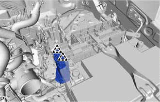
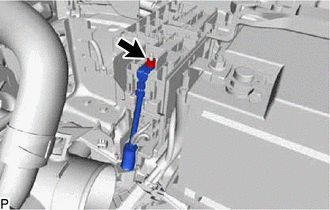
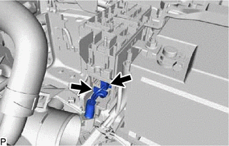
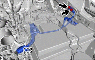
DISCONNECT ENGINE WIRE
-
Remove the ECM.
-
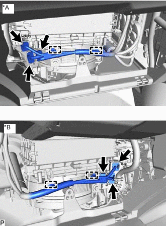
*A for LHD *B for RHD Detach the 2 clamps and disconnect the 3 connectors from the instrument panel wire.
-
*A for LHD *B for RHD Disconnect the connector from the engine room main wire.
-
*A for LHD *B for RHD Detach the clamp and disconnect the 4 connectors from the glow plug controller.
-
*A for LHD *B for RHD Detach the clamp and disconnect the engine wire from the bracket.
-
*A for LHD *B for RHD Detach the grommet and pull out the engine wire from the cabin.
-
-
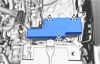
REMOVE AIR CLEANER CAP AND HOSE
-
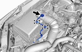
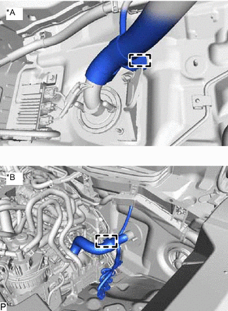
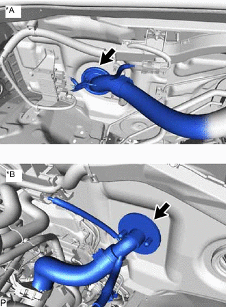
Detach the 2 clamps and disconnect the connector from the mass air flow meter.
-
Loosen the hose clamp.
-
Detach the 4 clips and remove the air cleaner cap and hose.
-
-
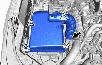
REMOVE AIR CLEANER FILTER ELEMENT SUB-ASSEMBLY
-
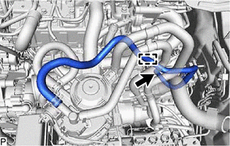
REMOVE NO. 1 AIR HOSE
-
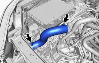
Slide the 2 clamps and remove the No. 1 air hose from the compressor outlet elbow and air tube.
-
-
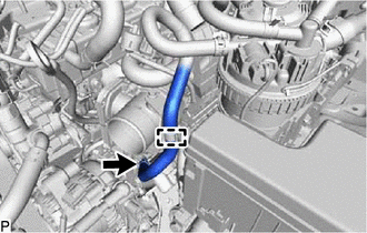
REMOVE NO. 4 AIR HOSE
-
Slide the clamp and disconnect the oil return hose from the engine oil level dipstick guide assembly.
-
Slide the 2 clamps and remove the No. 4 air hose from the No. 2 air tube and intercooler air tube.
-
-
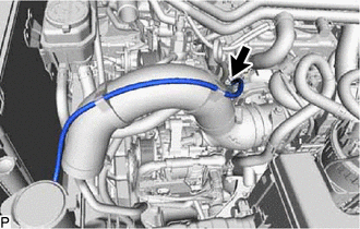
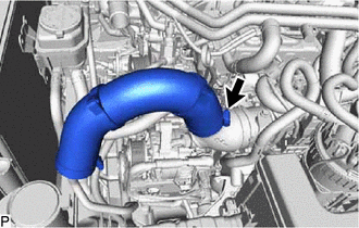
REMOVE INTERCOOLER AIR TUBE
-
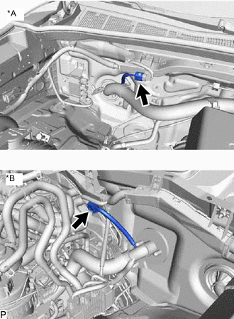
Disconnect the connector from the intake air temperature sensor.
-
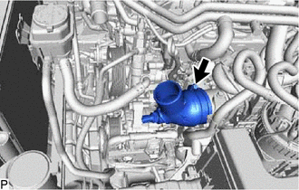
Slide the clamp and remove intercooler air tube from the diesel throttle body assembly.
-
-
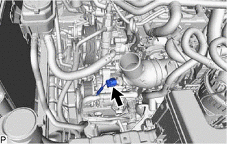
REMOVE FUEL FILTER ASSEMBLY
-
REMOVE NO. 1 FUEL HOSE
-
Detach the clamp from the No. 1 fuel hose.
-
Slide the clamp and disconnect the No. 1 fuel hose from the No. 2 fuel pipe.
-
-
REMOVE NO. 2 FUEL HOSE
-
Detach the clamp from the No. 2 fuel hose.
-
Slide the clamp and disconnect the No. 2 fuel hose from the No. 3 nozzle leakage pipe assembly.
-
-
DISCONNECT WIRE HARNESS
-
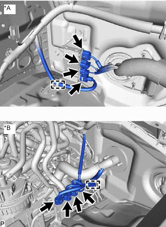
Detach the 3 clips and remove the No. 1 relay block cover upper from the engine room relay block.
-
Detach the 2 clips and remove the No. 1 relay block cover side from the engine room relay block sub-assembly.
-
Remove the nut and disconnect the wire to wire from the engine room relay block sub-assembly.
-
Disconnect the 2 connectors from the engine room relay block sub-assembly.
-
Detach the clamp and remove the 2 bolts and disconnect the No. 2 engine wire.
-
Remove the nut and disconnect the engine room main wire from the battery positive cable.
-
-
REMOVE BATTERY CLAMP SUB-ASSEMBLY
-
Loosen the 2 nuts and remove the battery clamp sub-assembly from the battery.
-
-
REMOVE BATTERY
-
REMOVE BATTERY TRAY
-
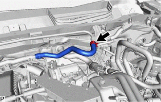
DISCONNECT WATER HOSE SUB-ASSEMBLY
-
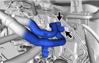
Slide the 2 clamps and disconnect the water hose sub-assembly from the air conditioning unit assembly.
-
-
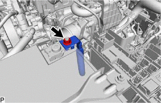
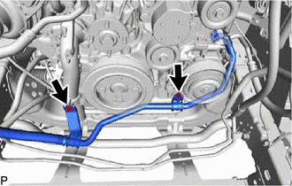
DISCONNECT VANE PUMP ASSEMBLY
-
Disconnect the connector from the power steering oil pressure switch.
-
Remove the 2 bolt and disconnect the vane pump assembly from the generator bracket.
-
-
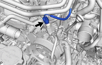
DISCONNECT UNION TO CONNECTOR TUBE HOSE
-
Slide the clamp and disconnect the union to connector tube hose from the No. 1 hose to hose tube.
-
-
REMOVE GENERATOR ASSEMBLY
-
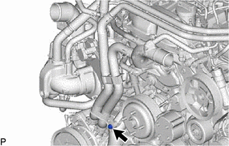
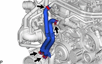
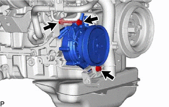
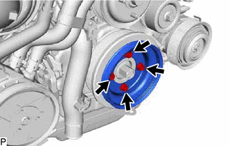
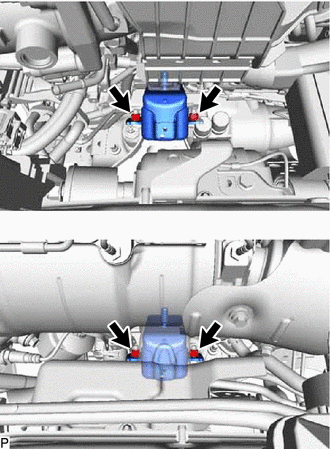
DISCONNECT COOLER COMPRESSOR ASSEMBLY
-
Remove the 2 bolts and disconnect the suction hose sub-assembly from the water inlet and timing chain cover.
-
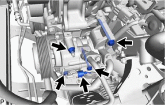
Disconnect the connector from the cooler compressor assembly.
-
Remove the 2 bolt and 2 nuts.
-
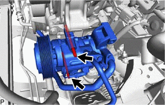
Using an E8 "TORX" socket wrench, remove the 2 stud bolts and disconnect the cooler compressor assembly from the compressor mounting bracket.
-
-
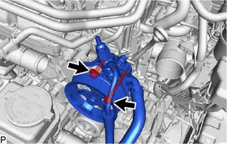
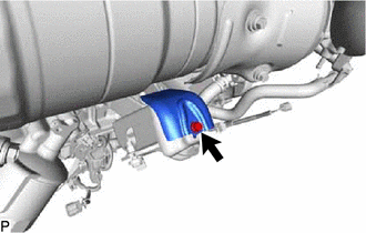
REMOVE WATER HOSE SUB-ASSEMBLY (w/ Viscous Heater)
-
Remove the bolt and disconnect the water hose from the water inlet.
-
Slide the 4 clamps and remove the water hose sub-assembly from the viscous heater with magnet clutch assembly, No. 2 water pipe and water outlet sub-assembly.
-
-
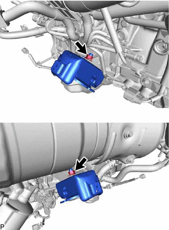
REMOVE VISCOUS HEATER WITH MAGNET CLUTCH ASSEMBLY (w/ Viscous Heater)
-
Disconnect the connector from the viscous heater with magnet clutch assembly.
-
Remove the 2 bolts, nut and viscous heater with magnet clutch assembly from the No. 1 viscous heater bracket.
-
-
REMOVE FRONT EXHAUST PIPE ASSEMBLY
-
REMOVE FRONT PROPELLER SHAFT ASSEMBLY (for 4WD)
-
REMOVE PROPELLER WITH CENTER BEARING SHAFT ASSEMBLY
-
REMOVE MANUAL TRANSMISSION UNIT ASSEMBLY (for Manual Transmission)
-
for R151:
-
for RC60:
-
for RC60F:
-
-
REMOVE DRIVE PLATE AND TORQUE CONVERTER CLUTCH SETTING BOLT (for Automatic Transmission)
-
REMOVE AUTOMATIC TRANSMISSION ASSEMBLY (for Automatic Transmission)
-
REMOVE CLUTCH COVER ASSEMBLY (for Manual Transmission)
-
for R151:
-
for RC60:
-
-
REMOVE CLUTCH DISC ASSEMBLY (for Manual Transmission)
-
for R151:
-
for RC60:
-
-
REMOVE FLYWHEEL SUB-ASSEMBLY
-
w/ Viscous Heater:
Remove the 4 bolts, viscous heater crankshaft pulley and crankshaft pulley cover from the crankshaft pulley.
-
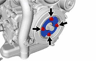
w/o Viscous Heater:
Remove the 4 bolts and crankshaft pulley cover from the crankshaft pulley.
-
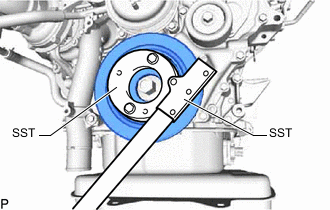
Using SST, hold the crankshaft pulley.
- SST
- 09213-58014 ( 91551-80840 )
- 09330-00021
-
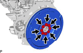
for Manual Transmission:
Remove the 8 bolts and flywheel sub-assembly from the crankshaft.
-
for Automatic Transmission:
Remove the 8 bolts, rear drive plate spacer, pump impeller drive plate and flywheel sub-assembly from the crankshaft.
-
-
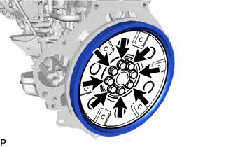
REMOVE REAR END PLATE
-
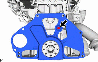
Remove the bolt and rear end plate from the cylinder block sub-assembly.
-
-
INSTALL ENGINE HANGER
-

*1 No. 1 Engine Hanger Upper *2 No. 2 Engine Hanger Install the No. 1 engine hanger upper and No. 2 engine hanger with the 3 bolts as shown in the illustration.
- Torque:
- for No. 1 engine hanger upper
- 29 N*m { 296 kgf*cm, 21 ft.*lbf }
- for No. 2 engine hanger
- 26 N*m { 265 kgf*cm, 19 ft.*lbf }
Tech Tips
No. 1 Engine Hanger Upper 12284-11010 or 12284-11020 No. 2 Engine Hanger 12282-11080 or 12282-11090 Bolt 90119-T0073 or 91552-81025 and 90119-T0219 or, 91672-80835
-
-
REMOVE ENGINE ASSEMBLY
-
Attach an engine sling device and hang the engine assembly with a chain block.
-
Remove the 4 bolts and 4 nuts from the body.
-
Remove the engine assembly by operating the engine sling device and chain block.
Note
-
Make sure that the engine assembly is clear of all wiring and hoses.
-
While lowering the engine assembly from the vehicle, do not allow it to contact the vehicle.
-
-
-
INSTALL ENGINE ASSEMBLY TO ENGINE STAND
Note
-
Pay attention to the angle of the sling device as the engine assembly or engine hangers may be damaged or deformed if the angle is incorrect.
-
With the exception of installing the engine assembly to an engine stand or removing the engine assembly from an engine stand, do not perform any work on the engine assembly while it is suspended, as doing so is dangerous.
-
Install the engine assembly to engine stand with the bolts.
-
Remove the 3 bolts, No. 1 engine hanger upper and No. 2 engine hanger.
-
-
REMOVE ENGINE WIRE
-
Remove the engine wire from the engine assembly.
-
-
REMOVE FRONT ENGINE MOUNTING INSULATOR RH
-
Remove the bolt and front engine mounting insulator RH from the front engine mounting insulator.
-
-
REMOVE FRONT ENGINE MOUNTING INSULATOR
-
Remove the 2 nuts and 2 front engine mounting insulators from the 2 front engine mounting brackets.
-