FUEL FILTER REPLACEMENT
CAUTION / NOTICE / HINT
Tech Tips
-
When replacing the fuel filter element assembly, use TOYOTA genuine parts.
-
When replacing the fuel filter element assembly, clean the fuel filter case and remove dirt completely.
PROCEDURE
-
REMOVE FUEL FILTER ELEMENT ASSEMBLY
Tech Tips
Replacement of the fuel filter element assembly can be performed with the fuel filter installed to the fuel filter bracket.
-
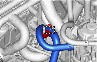
Detach the clamp and disconnect the No. 1 fuel hose from the No. 2 fuel pipe clamp.
-
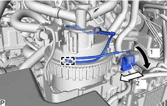
Disconnect the clamp and slide the lead wire as shown in the illustration to remove it.
-
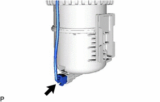
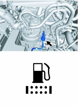
Disconnect the level warning switch connector.
-

Slide the fuel filter assembly and lift it up.
-
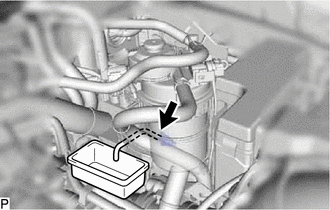
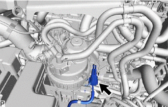
Connect a hose to the drain cock. Place the other end of the hose into a container under the drain cock.
-
Loosen the drain cock to drain fuel.
-
Tighten the drain cock by hand.
-
Disconnect a hose from the drain cock.
-
Disconnect the clogging switch connector.
-
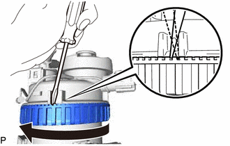
Using a screwdriver as a lever, loosen the fastener nut until it can be loosened by hand.
-
Fully loosen the fastener nut by hand.
-
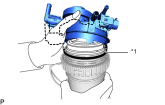
*1 O-ring To remove the fuel filter cap, pull up one side of the fuel filter cap, and then lift it off.
-
Remove the fuel filter element assembly from the fuel filter case.
-
Remove the O-ring from the fuel filter case.
-
-
INSTALL FUEL FILTER ELEMENT ASSEMBLY
-

*1 O-ring *2 Fuel Filter Element Assembly Install a new O-ring to the fuel filter case.
-
Install the fuel filter element assembly to the fuel filter case.
-
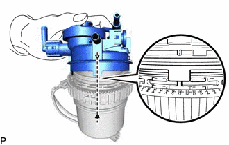
Align the mark on the fuel filter cap and the mark on the fuel filter case.
-
Push the fuel filter cap onto the fuel filter case by hand.
Standard clearance (A) 1.5 mm (0.0590 in.) or less Tech Tips
The clearance between the fuel filter cap and fuel filter case should be even around the entire circumference of the fuel filter cap and fuel filter case.
-
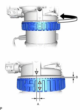
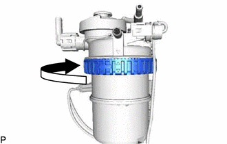
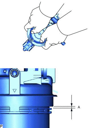
Turn the fastener nut until a "click" sound is heard.
Tech Tips
Just before the marks of the fuel filter case and nut align, the fastener nut will become more difficult to turn. Use a screwdriver as a lever to turn the fastener nut.
-
Measure the distance between the marks on the fuel filter cap and fuel filter case, and the clearance between the fuel filter cap and fuel filter case.
Standard distance (A) 1.0 mm (0.0393 in.) or more Standard clearance (B) 1.0 mm (0.0393 in.) or less -
Connect the clogging switch connector.
-
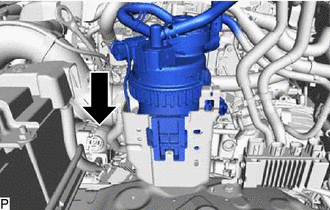
Slide the fuel filter assembly to install it.
-
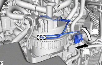
Attach the clamp and slide the lead wire as shown in the illustration to install it.
-
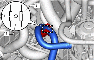
*1 No. 1 Fuel Hose *2 No. 2 Fuel Pipe Clamp *a Paint Mark Attach the clamp and connect the No. 1 fuel hose to the No. 2 fuel pipe clamp.
Tech Tips
Make sure that the paint mark of the No. 1 fuel hose is positioned as shown in the illustration.
-
-
RESET FUEL SYSTEM WARNING LIGHT
-
Turn the ignition switch to ON.
-
After turning the ignition switch to ON, connect the level warning switch connector no sooner than 3 seconds have passed but no later than 60 seconds have passed.
-
Check that the combination meter's fuel system warning light turns off.
-
-
BLEED AIR FROM FUEL SYSTEM
-
INSPECT FOR FUEL LEAK