ECD SYSTEM (w/o EGR Cooler), Diagnostic DTC:P0400
| DTC Code | DTC Name |
|---|---|
| P0400 | Exhaust Gas Recirculation Flow |
DESCRIPTION
The EGR system recirculates exhaust gases, and adjusts the volume of the exhaust gases to the proper level depending on driving conditions. The recirculated gas mixes with the intake air, allowing the EGR system to slow down engine combustion and lower the combustion temperature. This helps reduce NOx emissions.
In order to increase circulation efficiency, the ECM adjusts the lift amount of the EGR valve and throttle valve.
| DTC No. | DTC Detection Condition | Trouble Area |
|---|---|---|
| P0400 | When either condition below is met:
|
|
Tech Tips
DTC detection is not performed for 4 seconds after the brake switch is turned ON and OFF.
MONITOR DESCRIPTION
-
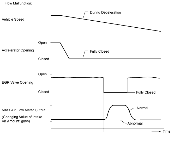
If the EGR valve assembly is forcibly operated but the intake air amount does not vary, the ECM determines that the EGR valve assembly is malfunctioning. The ECM then illuminates the MIL.
-
If the EGR valve is forcibly operated during deceleration but the intake air amount does not vary, the ECM determines that the EGR valve is malfunctioning. The ECM then illuminates the MIL (2 trip detection logic).
Flow malfunction
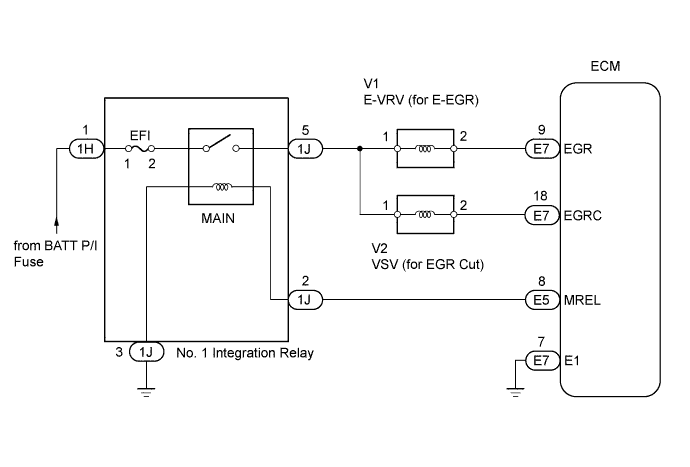
WIRING DIAGRAM
INSPECTION PROCEDURE
Tech Tips
Read freeze frame data using the intelligent tester. Freeze frame data records the engine conditions when a malfunction is detected. When troubleshooting, freeze frame data can help determine if the vehicle was moving or stationary, if the engine was warmed up or not, and other data from the time the malfunction occurred.
Note
After replacing the ECM, the new ECM needs registration Click here and initialization Click here.
PROCEDURE
-
CHECK OTHER DTC OUTPUT
-
Connect the intelligent tester to the DLC3.
-
Turn the ignition switch ON and turn the intelligent tester ON.
-
Enter the following menus: Powertrain / Engine and ECT / DTC.
-
Read DTCs.
Result Display (DTC output) Proceed to P0400 A P0400 and other DTCs B Tech Tips
If codes other than P0400 are output, perform troubleshooting for those DTCs first.
B 
GO TO DTC CHART Click here
A 
-
-
PERFORM ACTIVE TEST USING INTELLIGENT TESTER (ACTIVATE THE EGR VALVE CLOSE)
-
Connect the intelligent tester to the DLC3.
-
Start the engine and warm it up (engine coolant temperature is 70°C (158°F) or higher) with the A/C switch and all accessory switches off.
-
Turn the ignition switch off. Wait for 30 seconds, and then restart the engine.
-
Turn the tester on.
-
Select the following menus: Powertrain / Engine and ECT / Data List / MAF.
-
Read the MAF value displayed on the tester while the engine is idling.
-
Select the following menus: Powertrain / Engine and ECT / Active Test / Activate the EGR Valve Close.
-
Read the MAF value when the EGR valve is closed using the Active Test function.
Tech Tips
-
If idling continues for 15 minutes or more, the EGR valve target opening angle becomes 0% (EGR valve fully closed). As this makes diagnosis impossible, it becomes necessary to drive the vehicle or restart the engine.
-
Before performing the diagnosis, confirm that the EGR valve target opening angle is not 0%.
Result Active Test Result Proceed to Activate the EGR Valve Close:
Off (Open) to on (Closed)
MAF value does not change A MAF value changes B Note
As the measured values may differ from those shown below due to factors such as differences in measuring environments and changes in vehicle condition due to aging, do not use these values to determine whether the vehicle is malfunctioning or not.
Tech Tips
The problem may be a temporary one, due to the entry of deposits or foreign matter. Check that there are no deposits or foreign matter in the electric vacuum regulating valve assembly, electric EGR control valve assembly or mass air flow meter.
Reference EGR Valve Condition (Opening) Measuring Condition MAF (Reference) Open (55%)
-
Atmosphere pressure: 101 kPa
-
Intake air temperature: 30°C (86°F)
-
Engine coolant temperature: 88°C (190°F)
3.0 to 9.0 gm/s Closed (0%) 15 to 22 gm/s -
B 
INSPECT EGR VALVE ASSEMBLY Click here
A
-
-
INSPECT VACUUM PUMP ASSEMBLY
-
Check the negative pressure of the vacuum pump.
Standard More than 86.7 kPa (650 mmHg, 26 in.Hg)
NG
REPLACE VACUUM PUMP ASSEMBLY
OK
-
-
CHECK VACUUM HOSE
-
Check the vacuum hoses.
OK The hoses are not damaged and securely connected.
NG
REPLACE VACUUM HOSE
OK
-
-
INSPECT E-VRV FOR EGR
-
Inspect the E-VRV for EGR Click here.
NG
REPLACE ELECTRIC VACUUM REGULATING VALVE FOR EGR
OK
-
-
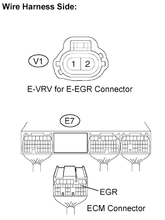
CHECK WIRE HARNESS (E-VRV FOR EGR - ECM)
-
Disconnect the V1 E-VRV for EGR connector.
-
Disconnect the E7 ECM connector.
-
Measure the resistance of the wire harness side connectors.
Standard resistance Tester Connection Specified Condition E7-9 (EGR) - V1-2 Below 1 Ω E7-9 (EGR) or V1-2 - Body ground 10 kΩ or higher
NG
REPAIR OR REPLACE HARNESS OR CONNECTOR
OK
-
-
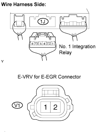
CHECK WIRE HARNESS (E-VRV FOR EGR - NO. 1 INTEGRATION RELAY (MAIN RELAY))
-
Remove the No. 1 integration relay from the engine room junction block.
-
Disconnect the 1J No. 1 integration relay connector.
-
Disconnect the V1 E-VRV connector.
-
Measure the resistance of the wire harness side connectors.
Standard resistance Tester Connection Specified Condition 1J-5 - V1-1 Below 1 Ω 1J-5 or V1-1 - Body ground 10 kΩ or higher
NG
REPAIR OR REPLACE HARNESS OR CONNECTOR
OK
-
-
INSPECT VSV FOR EGR CUT
-
Inspect the VSV for EGR cut Click here.
NG
REPLACE VACUUM SWITCHING VALVE FOR EGR CUT
OK
-
-
CHECK HARNESS AND CONNECTOR (VSV EGR CUT - ECM)
-
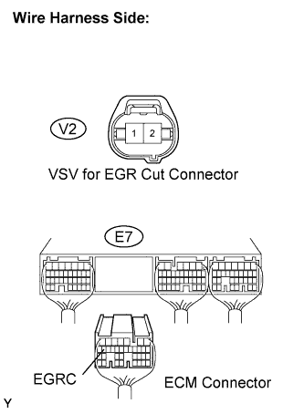
Disconnect the V2 VSV for EGR Cut connector.
-
Disconnect the E7 ECM connector.
-
Measure the resistance of the wire harness side connectors.
Standard resistance Tester Connection Specified Condition E7-18 (EGRC) - V2-2 Below 1 Ω E7-18 (EGRC) or V2-2 - Body ground 10 kΩ or higher
NG
REPAIR OR REPLACE HARNESS OR CONNECTOR
OK
-
-
CHECK HARNESS AND CONNECTOR (VSV FOR EGR CUT - NO. 1 INTEGRATION RELAY (MAIN RELAY))
-
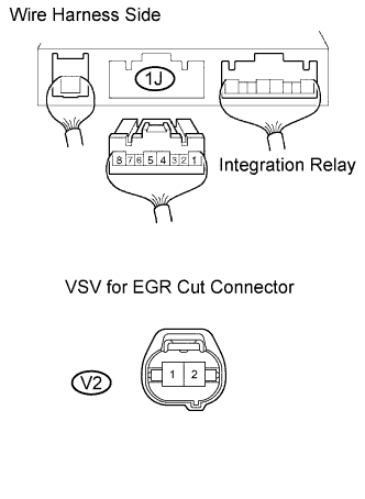
Remove the No. 1 integration relay from the engine room junction block.
-
Disconnect the 1J No. 1 integration relay connector.
-
Disconnect the V2 VSV for EGR Cut connector.
-
Measure the resistance of the wire harness side connectors.
Standard resistance Tester Connection Specified Condition 1J-5 - V2-1 Below 1 Ω 1J-5 or V2-1 - Body ground 10 kΩ or higher
NG
REPAIR OR REPLACE HARNESS OR CONNECTOR
OK
-
-
INSPECT EGR VALVE ASSEMBLY
-
Inspect the EGR valve assembly Click here.
Tech Tips
-
If there are any deposits adhering to the valve, clean the valve.
-
When inspecting the EGR valve, make sure that the valve is fully closed.
-
OK
CHECK FOR BLOCKAGE IN EGR GAS PASSAGE (EXHAUST MANIFOLD - EGR VALVE ASSEMBLY) Click here
NG
REPLACE EGR VALVE ASSEMBLY Click here
-
-
REPLACE EGR VALVE ASSEMBLY
-
Replace the EGR valve assembly Click here.
NEXT
-
-
CHECK FOR BLOCKAGE IN EGR GAS PASSAGE (EXHAUST MANIFOLD - EGR VALVE ASSEMBLY)
-
Check for blockage in the EGR gas passage between the exhaust manifold and EGR valve assembly.
OK No blockage in the EGR gas passage Result Result Proceed to NG A OK B
B
CHECK WHETHER DTC OUTPUT RECURS Click here
A
-
-
REPAIR OR REPLACE MALFUNCTIONING PARTS, COMPONENT AND AREA
-
Repair or replace the malfunctioning parts, component and area.
NEXT
-
-
CHECK WHETHER DTC OUTPUT RECURS
-
Connect the intelligent tester to the DLC3.
-
Turn the ignition switch to ON and turn the tester on.
-
Start the engine and warm it up until the engine coolant temperature reaches 80°C (176°F).
-
Move the shift lever to 2nd gear and decelerate from a speed of 50 km/h (31 mph) or more (fully closing the accelerator for approximately 5 seconds or more).
-
Select the following menu items: Powertrain / Engine and ECT / DTC.
-
Read the DTC.
Result Display (DTC Output) Proceed to P0400 A No output B
B
END
A
-
-
REPLACE ECM
-
Replace the ECM Click here.
NEXT
-
-
CONFIRM WHETHER MALFUNCTION HAS BEEN SUCCESSFULLY REPAIRED
-
Connect the intelligent tester to the DLC3.
-
Turn the ignition switch to ON and turn the tester on.
-
Start the engine and warm it up until the engine coolant temperature reaches 80°C (176°F).
-
Move the shift lever to 2nd gear and decelerate from a speed of 50 km/h (31 mph) or more (fully closing the accelerator for approximately 5 seconds or more).
-
Select the following menu items: Powertrain / Engine and ECT / DTC.
-
Confirm that the DTC is not output again.
Tech Tips
If the DTC is output again, the mass air flow meter may be malfunctioning.
NEXT 
END
-