CYLINDER HEAD GASKET REMOVAL
CAUTION / NOTICE / HINT
The necessary procedures (adjustment, calibration, initialization, or registration) that must be performed after parts are removed, installed, or replaced during the cylinder head gasket removal/installation are shown below.
| Replaced Part or Performed Procedure | Necessary Procedure | Effect/Inoperative Function when Necessary Procedure not Performed | Link |
|---|---|---|---|
| Battery terminal is disconnected/reconnected | Drive the vehicle until stop and start control is permitted (approximately 5 to 60 minutes) | Stop and start system | |
| Memorize steering angle neutral point | LKA/LDA system | ||
| Parking support brake system*1 | |||
| Pre-collision system | |||
| Adaptive high beam system | |||
Lighting system (EXT) |
|||
| Variable gear ratio steering system | |||
| Parking assist monitor system | |||
| Panoramic view monitor system | |||
| Initialize rear door sunshade system | Rear door sunshade system | ||
| Initialize power trunk lid system | Power trunk lid system | ||
|
Inspection after repairs |
|
w/ Canister Pump Module: w/o Canister Pump Module: |
| Piston ring | Inspection after repair |
|
|
Heavy Knock History |
- | ||
| Front exhaust pipe assembly*2 | GPF deposition value clear |
|
|
| Replacement of engine assembly | Inspection after repair |
|
w/ Canister Pump Module: w/o Canister Pump Module: |
|
|
for AGA0E: for AGA0F: |
|
| ECM | Vehicle Identification Number (VIN) registration | DTC P063051 is output | w/ Canister Pump Module: w/o Canister Pump Module: |
Heavy Knock History |
- | ||
| Parts between the steering wheel and tires have been removed/installed, replaced or adjusted | Perform Actuator Angle Neutral Point Calibration and Initialization |
|
|
| Suspension, tires, etc |
|
Parking support brake system | |
|
Panoramic view monitor system | ||
| Rear television camera assembly optical axis (Back camera position setting) | Parking assist monitor system |
Click here Click here
*2: w/ Gasoline Particulate Filter
Note
This procedure includes the removal of small-head bolts. Refer to Small-Head Bolts of Basic Repair Hint to identify the small-head bolts.
PROCEDURE
-
REMOVE ENGINE ASSEMBLY WITH TRANSMISSION
-
REMOVE FRONT NO. 1 ENGINE MOUNTING BRACKET RH (for 2WD)
-
REMOVE DIRECT FUEL INJECTOR ASSEMBLY (for High Pressure)
-
REMOVE NO. 1 TURBOCHARGER SUB-ASSEMBLY
-
REMOVE NO. 2 TURBOCHARGER SUB-ASSEMBLY
-
REMOVE TIMING CHAIN OR BELT COVER SUB-ASSEMBLY
-
REMOVE OIL PUMP DRIVE CHAIN SUB-ASSEMBLY
-
SET NO. 1 CYLINDER TO TDC/COMPRESSION
-
REMOVE NO. 1 CHAIN TENSIONER ASSEMBLY
-
REMOVE CHAIN TENSIONER SLIPPER
-
REMOVE NO. 1 CHAIN SUB-ASSEMBLY
-
REMOVE IDLE SPROCKET ASSEMBLY
-
REMOVE NO. 1 CHAIN VIBRATION DAMPER
-
REMOVE NO. 2 CHAIN VIBRATION DAMPER
-
REMOVE CRANKSHAFT TIMING GEAR OR SPROCKET
-
REMOVE TIMING CHAIN COVER ASSEMBLY
-
REMOVE VACUUM PUMP ASSEMBLY
-
REMOVE CAMSHAFT BEARING CAP (for Bank 1)
-
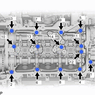
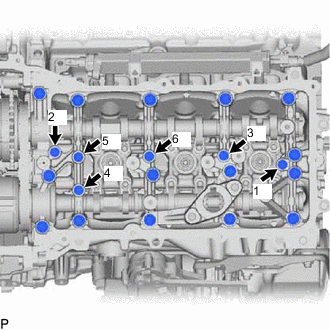
Uniformly loosen and remove the 14 bearing cap bolts in several steps and in the sequence shown in the illustration.
-
Remove the fuel pump lifter housing RH.
-
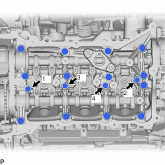
Uniformly loosen and remove the 4 bearing cap bolts in several steps and in the sequence shown in the illustration.
Note
Uniformly loosen the bolts while keeping the camshaft level.
-
Remove the camshaft bearing caps.
Tech Tips
-
Remove the No. 1 camshaft bearing cap while holding down the chain plunger of the No. 2 chain tensioner assembly.
-
Arrange the removed parts so that they can be reinstalled in their original locations.
-
-
-
REMOVE INTAKE CAMSHAFT SUB-ASSEMBLY RH
-
Remove the intake camshaft sub-assembly RH from the camshaft housing sub-assembly RH.
-
Remove the No. 2 chain sub-assembly from the camshaft timing gear assembly and exhaust camshaft timing gear assembly.
-
-
REMOVE EXHAUST CAMSHAFT SUB-ASSEMBLY RH
-
Remove the exhaust camshaft sub-assembly RH from the camshaft housing sub-assembly RH.
-
-
REMOVE CAMSHAFT HOUSING SUB-ASSEMBLY RH
-
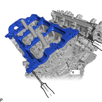
*a Protective Tape Remove the camshaft housing sub-assembly RH by prying between the cylinder head sub-assembly and camshaft housing sub-assembly RH with a screwdriver.
Note
Be careful not to damage the contact surfaces of the cylinder head sub-assembly and camshaft housing sub-assembly RH.
Tech Tips
Tape the screwdriver tip before use.
-
-
REMOVE CAMSHAFT BEARING CAP (for Bank 2)
-
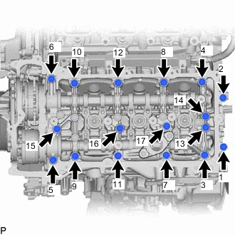
Uniformly loosen and remove the 17 bearing cap bolts in several steps and in the sequence shown in the illustration.
-
Remove the fuel pump lifter housing LH.
-
Uniformly loosen and remove the 6 bearing cap bolts in several steps and in the sequence shown in the illustration.
Note
Uniformly loosen the bolts while keeping the camshaft level.
-
Remove the camshaft bearing caps.
Tech Tips
-
Remove the No. 5 camshaft bearing cap while holding down the chain plunger of the No. 3 chain tensioner assembly.
-
Arrange the removed parts so that they can be reinstalled in their original locations.
-
-
-
REMOVE INTAKE CAMSHAFT SUB-ASSEMBLY LH
-
Remove the intake camshaft sub-assembly LH from the camshaft housing sub-assembly LH.
-
Remove the No. 2 chain sub-assembly from the camshaft timing gear assembly and exhaust camshaft timing gear assembly.
-
-
REMOVE EXHAUST CAMSHAFT SUB-ASSEMBLY LH
-
Remove the exhaust camshaft sub-assembly LH from the camshaft housing sub-assembly LH.
-
-
REMOVE CAMSHAFT HOUSING SUB-ASSEMBLY LH
-
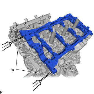
*a Protective Tape Remove the camshaft housing sub-assembly LH by prying between the cylinder head LH and camshaft housing sub-assembly LH with a screwdriver.
Note
Be careful not to damage the contact surfaces of the cylinder head and camshaft housing sub-assembly LH.
Tech Tips
Tape the screwdriver tip before use.
-
-
REMOVE VALVE ROCKER ARM SUB-ASSEMBLY
-
Remove the 24 valve rocker arm sub-assemblies.
Tech Tips
Arrange the removed parts in the correct order.
-
-
REMOVE VALVE LASH ADJUSTER ASSEMBLY
-
Remove the 24 valve lash adjuster assemblies from the cylinder head sub-assembly.
Tech Tips
Arrange the removed parts in the correct order.
-
-
REMOVE VALVE STEM CAP
-
Remove the 24 valve stem caps.
Tech Tips
Arrange the removed parts in the correct order.
-
-
REMOVE CYLINDER HEAD SUB-ASSEMBLY RH
-
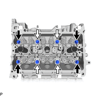

Bolt Length 140 mm (5.51 in.) 
Bolt Length 150 mm (5.90 in.) Using a 12 mm socket wrench, uniformly loosen the 8 bolts in the sequence shown in the illustration. Remove the 8 cylinder head set bolts and plate washers.
Note
-
Be careful not to drop washers into the cylinder head sub-assembly RH.
-
Cylinder head sub-assembly warpage or cracking could result from removing bolts in an incorrect order.
Tech Tips
Be sure to keep separate the removed parts for each installation position.
-
-
Remove the cylinder head sub-assembly RH.
-
-
REMOVE CYLINDER HEAD GASKET RH
-
Remove the cylinder head gasket RH from the cylinder block sub-assembly RH.
-
-
REMOVE CYLINDER HEAD SUB-ASSEMBLY LH
-
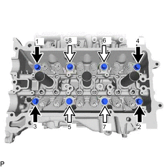
Bolt Length 140 mm (5.51 in.) Bolt Length 150 mm (5.90 in.) Using a 12 mm socket wrench, uniformly loosen the 8 bolts in the sequence shown in the illustration. Remove the 8 cylinder head set bolts and plate washers.
Note
-
Be careful not to drop washers into the cylinder head sub-assembly LH.
-
Cylinder head sub-assembly warpage or cracking could result from removing bolts in an incorrect order.
Tech Tips
Be sure to keep separate the removed parts for each installation position.
-
-
Remove the cylinder head sub-assembly LH.
-
-
REMOVE CYLINDER HEAD GASKET LH
-
Remove the cylinder head gasket LH from the cylinder block sub-assembly LH.
-
-
INSPECT CYLINDER HEAD SET BOLT
-
INSPECT CYLINDER HEAD SUB-ASSEMBLY