CAMSHAFT REMOVAL

CAUTION / NOTICE / HINT
The necessary procedures (adjustment, calibration, initialization, or registration) that must be performed after parts are removed and installed, or replaced during camshaft removal/installation are shown below.
| Replaced Part or Performed Procedure | Necessary Procedure | Effect/Inoperative Function when Necessary Procedure not Performed | Link | |
|---|---|---|---|---|
| Battery terminal is disconnected/reconnected | Memorize steering angle neutral point | LKA/LDA System | ||
| Intelligent Clearance Sonar System*4 | ||||
| Pre-crash Safety System | ||||
| Lighting System (EXT)
|
||||
| Adaptive High Beam System | ||||
| Drive the vehicle until stop and start control is permitted (approximately 15 to 60 minutes) | Stop and Start System | |||
| Memorize steering angle neutral point | Parking Assist Monitor System (w/ Parallel Parking Assist Function) | |||
| Parking Assist Monitor System (w/o Parallel Parking Assist Function) | ||||
| Panoramic View Monitor System | ||||
| Initialize back door lock | Power Door Lock Control System | |||
| Reset back door close position | Power Back Door System | |||
| Replacement of ECM | Perform Vehicle Identification Number (VIN) or frame number registration |
|
Click here for Rear Air Fuel Ratio Sensor Click here for Rear Heated Oxygen Sensor |
|
| ECU Communication ID Registration (Immobiliser system) | Engine start function | See Service Bulletin for the registration method. | ||
| Perform code registration (Immobiliser system) |
|
|||
| Replacement of ECM (If possible, read the transaxle compensation code from the previous ECM) |
Possible to read transaxle compensation code | Perform the following procedures in the order shown:
|
|
Click here for Initialization (U661E) Click here for Registration (U661E) Click here for Initialization (U661F) Click here for Registration (U661F) |
| Impossible to read transaxle compensation code | Perform the following procedures in the order shown:
|
|||
for Rear Air Fuel Ratio Sensor |
Inspection After Repair |
|
||
for Rear Heated Oxygen Sensor |
Inspection After Repair |
|
||
| Replacement of starter assembly*1 Note When the starter assembly is replaced, "ST relay" and "ST NO. 2 relay" must be also replaced. |
Clear Number of Starter Operations | Stop and Start System | ||
| Replacement of battery*1 |
|
|||
|
Bleed the oil pump assembly with motor (continuously variable transaxle assembly) | |||
| Replacement of automatic transaxle assembly | Perform the following procedures in the order shown:
|
|
Click here for Initialization (U661E) Click here for Registration (U661E) Click here for Initialization (U661F) Click here for Registration (U661F) |
|
| Suspension, tires, etc.*2 |
|
|
||
| Rear television camera assembly optical axis (Back camera position setting) | Parking assist monitor system (w/ Parallel Parking Assist Function) | Click here for Initialization Click here for Calibration |
||
| Parking assist monitor system (w/o parallel parking assist function) | Click here for Initialization Click here for Calibration |
|||
|
Panoramic view monitor system | Click here for Initialization Click here for Calibration |
||
| Initialize headlight ECU sub-assembly LH |
|
|||
| Front wheel alignment adjustment |
|
|
||
*2: The vehicle height changes because of suspension or tire replacement
*3: w/ TFT Meter Type
*4: When performing learning using the GTS.
Click here Click here
PROCEDURE
-
INSTALL ENGINE TO ENGINE STAND
-
REMOVE ENGINE HANGERS
-
REMOVE IGNITION COIL ASSEMBLY
-
REMOVE V-RIBBED BELT
-
DISCONNECT ENGINE WIRE
-
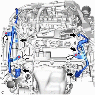

Connector 
Bolt Disconnect the 5 connectors.
-
Remove the 3 bolts and disconnect the engine wire.
-
-
REMOVE FUEL PUMP ASSEMBLY (for High Pressure)
-
REMOVE CYLINDER HEAD COVER SUB-ASSEMBLY
-
DISCONNECT NO. 2 VACUUM TRANSMITTING HOSE ASSEMBLY
-
REMOVE VACUUM PUMP ASSEMBLY
-
SET NO. 1 CYLINDER TO TDC/COMPRESSION
-
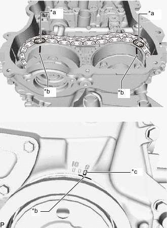
*a Paint Mark *b Timing Mark *c Timing Notch (Groove) Turn the crankshaft pulley until its timing notch (groove) and the timing mark "0" of the timing chain cover assembly are aligned.
-
Check that each timing mark of the camshaft timing gear assembly and camshaft timing exhaust gear assembly is positioned as shown in the illustration. If not, turn the crankshaft 1 revolution (360°) to align the timing marks as shown in the illustration.
-
Place paint marks on the chain sub-assembly in alignment with the timing marks on the camshaft timing gear assembly and camshaft timing exhaust gear assembly.
-
-
REMOVE TIMING CHAIN COVER PLATE
-
REMOVE NO. 1 CHAIN TENSIONER ASSEMBLY
-
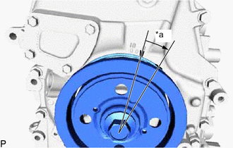
*a Approximately 15° Turn the crankshaft pulley approximately 15° clockwise.
-
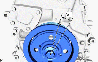
*a Approximately 15° Turn the crankshaft pulley approximately 15° counterclockwise.
-
*a Stopper Plate *b Pin Align the holes of the stopper plate and No. 1 chain tensioner assembly, and insert a pin into the stopper plate hole to lock the No. 1 chain tensioner assembly.
-
*a Approximately 15° Turn the crankshaft pulley approximately 15° clockwise.
-
Remove the bolt, nut, No. 1 chain tensioner assembly and gasket.
Note
Be careful not to drop the gasket into the timing chain cover assembly.
-
*a Approximately 15° Turn the crankshaft pulley approximately 15° counterclockwise.
-
-
REMOVE TIMING CHAIN GUIDE
-
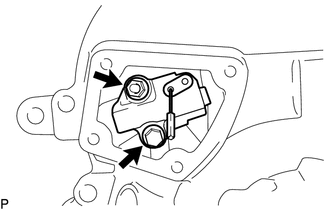
REMOVE CAMSHAFT TIMING OIL CONTROL SOLENOID ASSEMBLY
-
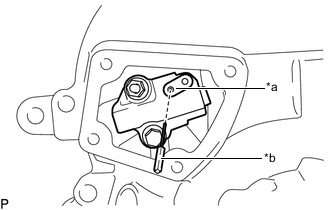
REMOVE CAMSHAFT TIMING GEAR BOLT
-
*a Hold *b Turn Using a wrench to hold the hexagonal portion of the camshaft, remove the camshaft timing gear bolt from the camshaft.
Note
Be careful not to damage the cylinder head sub-assembly or spark plug tube with the wrench.
-
-
REMOVE CAMSHAFT BEARING CAP
-
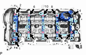
Remove the 11 bolts in several steps in the order shown in the illustration.
-
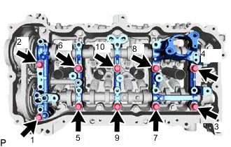
Remove the 10 bolts in several steps in the order shown in the illustration.
Note
Make sure to loosen the bolts evenly while holding the camshaft horizontally.
-
Remove the No. 1 camshaft bearing cap, No. 2 camshaft bearing cap, No. 3 camshaft bearing cap and No. 4 camshaft bearing cap.
Tech Tips
Arrange the removed parts in such a way that they can be reinstalled to their original locations.
-
-
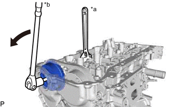
REMOVE CAMSHAFT
-
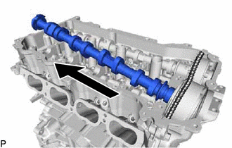
Raise the camshaft as shown in the illustration to remove it from the camshaft timing gear assembly.
Note
Be careful not to damage the camshaft or camshaft timing gear assembly with the wrench.
-
-
REMOVE CAMSHAFT TIMING GEAR ASSEMBLY
-
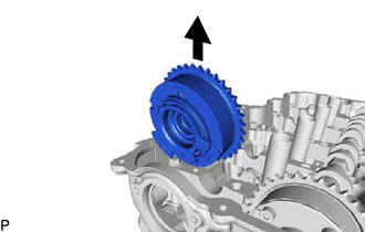
Remove the camshaft timing gear assembly.
Note
-
Do not disassemble the camshaft timing gear assembly.
-
Be careful not to damage the camshaft timing gear assembly with the wrench.
-
-
-
REMOVE NO. 2 CAMSHAFT
-
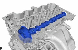
Hold up the chain sub-assembly and remove the No. 2 camshaft from the camshaft housing sub-assembly.
-
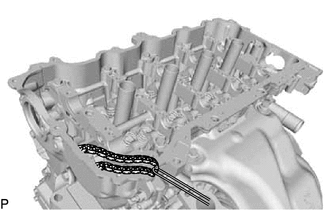
Suspend the chain sub-assembly with a string or equivalent as shown in the illustration.
Note
Be careful not to drop the chain sub-assembly into the timing chain cover assembly.
-
-
REMOVE CAMSHAFT TIMING EXHAUST GEAR ASSEMBLY
-
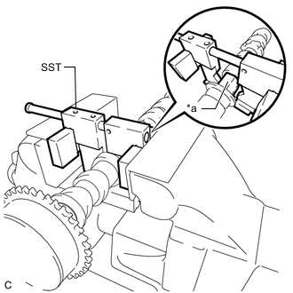
*a Hexagonal Portion Using SST, grip the hexagonal portion, and then secure the SST and No. 2 camshaft in a vise as shown in the illustration.
- SST
- 09212-31010
Note
-
Do not damage the No. 2 camshaft.
-
Never grip areas other than the hexagonal portion, as this may cause damage.
-
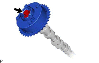
Remove the bolt and camshaft timing exhaust gear assembly.
Note
-
Do not disassemble the camshaft timing exhaust gear assembly.
-
Be careful not to damage the No. 2 camshaft and camshaft timing exhaust gear assembly.
-
-
-
REMOVE OIL CONTROL VALVE FILTER
-
REMOVE NO. 1 CAMSHAFT BEARING
-
REMOVE NO. 2 CAMSHAFT BEARING
-
INSPECT CAMSHAFT TIMING EXHAUST GEAR ASSEMBLY