| DTC Code | DTC Name |
|---|---|
| P0E2D00 | Hybrid/EV Battery Energy Control Module Hybrid/EV Battery Monitor Performance |
DESCRIPTION
The battery voltage sensor detects the cell voltage of the HV battery. The battery voltage sensor performs self diagnosis of the internal cell voltage detection circuit, and informs the battery ECU assembly of the result. The battery ECU assembly stores this DTC.
| DTC No. | Detection Item | DTC Detection Condition | Trouble Area | MIL | Warning Indicate |
|---|---|---|---|---|---|
| P0E2D00 | Hybrid/EV Battery Energy Control Module Hybrid/EV Battery Monitor Performance | The battery voltage sensor detects a malfunction of its internal HV battery cell voltage detection circuits. (1 trip detection logic) |
|
Comes on | Master Warning Light: Comes on |
| DTC No. | Data List |
|---|---|
| P0E2D00 | Hybrid Battery Cell 1 to 84 Voltage |
CONFIRMATION DRIVING PATTERN
After repair has been completed, clear the DTC and then check that the vehicle has returned to normal by performing the following All Readiness check procedure.
-
Connect the GTS to the DLC3.
-
Turn the power switch on (IG) and turn the GTS on.
-
Clear the DTCs (even if no DTCs are stored, perform the clear DTC procedure).
-
Turn the power switch off and wait for 2 minutes or more.
-
Turn the power switch on (IG) and turn the GTS on.
-
With the vehicle stopped and the shift position in P, turn the power switch on (IG) and wait for at least 70 seconds.
-
Turn the power switch on (READY) and without depressing the accelerator pedal, and while depressing the brake pedal, change the shift position to D and wait for 1 minutes. (Step A)
-
Drive the vehicle 0.5 m (1.6 ft.) forward and perform step A.
-
Drive the vehicle another 0.5 m (1.6 ft.) forward and perform step A. Repeat this procedure 5 times (minimum total driving distance: 2 m (6.6 ft.)).
-
Enter the following menus: Powertrain / HV Battery / Utility / All Readiness.
-
Check the DTC judgment result.
Tip:
-
If the judgment result shows NORMAL, the system is normal.
-
If the judgment result shows ABNORMAL, the system has a malfunction.
-
If the judgment result shows INCOMPLETE, perform driving pattern again.
-
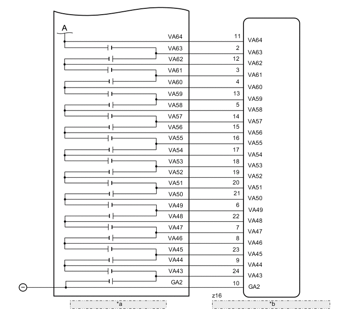
| *a | No. 2 HV Supply Stack Sub-assembly |
| *b | Battery Voltage Sensor (for Lower Side) |
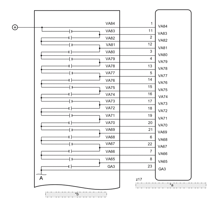
| *a | Battery Voltage Sensor (for Lower Side) |
| *b | No. 2 HV Supply Stack Sub-assembly |
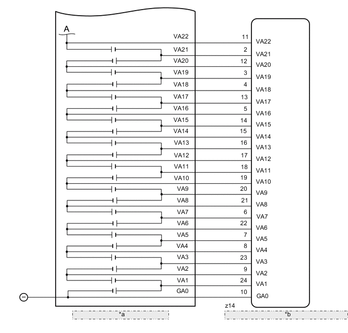
| *a | No.1 HV Supply Stack Sub-assembly |
| *b | Battery Voltage Sensor (for Upper Side) |
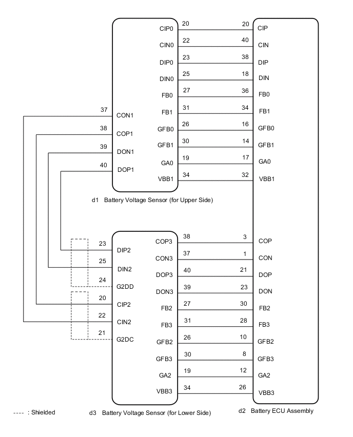
WIRING DIAGRAM
CAUTION / NOTICE / HINT
-

Before the following operations are conducted, take precautions to prevent electric shock by turning the power switch off, wearing insulated gloves, and removing the service plug grip from HV battery.
-
-
Inspecting the high-voltage system
-
Disconnecting the low voltage connector of the inverter with converter assembly
-
Disconnecting the low voltage connector of the HV battery
-
-
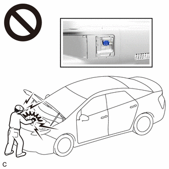
To prevent electric shock, make sure to remove the service plug grip to cut off the high voltage circuit before servicing the vehicle.
-
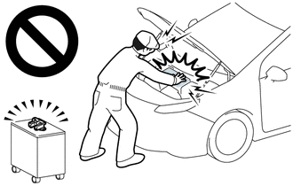
After removing the service plug grip from the HV battery, put it in your pocket to prevent other technicians from accidentally reconnecting it while you are working on the high-voltage system.
-
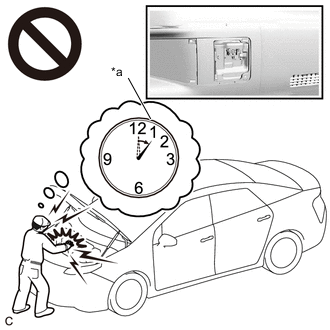
*a Without waiting for 10 minutes After removing the service plug grip, wait for at least 10 minutes before touching any of the high-voltage connectors or terminals. After waiting for 10 minutes, check the voltage at the terminals in the inspection point in the inverter with converter assembly. The voltage should be 0 V before beginning work.
Tip:Waiting for at least 10 minutes is required to discharge the high-voltage capacitor inside the inverter with converter assembly and the electric vehicle charger assembly.
-
Make sure to insulate the high-voltage connectors and terminals of the HV battery with insulating tape after removing it.
If the HV battery stored without insulating the connectors and terminals, electric shock or fire may result.
-
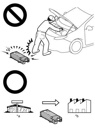
*a Dealer *b Battery Collection Agent When disposing of an HV battery, make sure to return it through an authorized collection agent who is capable of handling it safely. If the HV battery is returned via the manufacturer specified route, it will be returned properly and in a safe manner by an authorized collection agent.
-
-
Accidents such as electric shock may result if the HV battery is disposed of improperly or abandoned. Therefore, make sure to return all HV batteries through an authorized collection agent.
-
-
Before returning the HV battery, make sure to perform a recovery inspection.
-
Before returning the HV supply stack sub-assembly, make sure to perform a recovery inspection.
-
Make a note of the output DTCs as some of them may be necessary for recovery inspection of the HV battery and HV supply stack sub-assemblies.
-
After removing the HV battery, keep it away from water. Exposure to water may cause the HV battery to produce heat, resulting in a fire.
After turning the power switch off, waiting time may be required before disconnecting the cable from the negative (-) auxiliary battery terminal. Therefore, make sure to read the disconnecting the cable from the negative (-) auxiliary battery terminal notices before proceeding with work.
PROCEDURE
- Click here
CHECK DTC OUTPUT (HV BATTERY, HYBRID CONTROL)
-
Connect the GTS to the DLC3.
-
Turn the power switch on (IG).
-
Enter the following menus: Powertrain / HV Battery and Hybrid Control / Trouble Codes.
-
Check for DTCs.
- Powertrain > HV Battery > Trouble Codes
-
-
- Powertrain > Hybrid Control > Trouble Codes
-
-
Result Result Proceed to "P0E2D00" only is output, or DTCs except the ones in the table below are also output. A DTCs of hybrid battery system in the table below are output. B DTCs of hybrid control system in the table below are output. C System Relevant DTC Hybrid battery system P060A47 Hybrid/EV Battery Energy Control Module Monitoring Processor Watchdog / Safety MCU Failure P060B49 Hybrid/EV Battery Energy Control Module A/D Processing Internal Electronic Failure P060687 Hybrid/EV Battery Energy Control Module Processor to Monitoring Processor Missing Message P1A001C Hybrid Battery Stack 2 Cell Voltage Detection Voltage Out of Range P301A1C Hybrid Battery Stack 1 Cell Voltage Detection Voltage Out of Range Hybrid control system P0A1F94 Hybrid/EV Battery Energy Control Module Unexpected Operation P0AA649 *1 Hybrid/EV Battery Voltage System Isolation Internal Electronic Failure *1: If area specific insulation resistance malfunction DTCs (P1C7C49, P1C7D49, P1C7E49 or P1C7F49) are output, perform repairs according to each DTC.
-
Turn the power switch off.
- AClick here
- B
GO TO DTC CHART (HYBRID BATTERY SYSTEM)Click here
- C
GO TO DTC CHART (HYBRID CONTROL SYSTEM)Click here
-
- Click here
CHECK FREEZE FRAME DATA
-
Connect the GTS to the DLC3.
-
Turn the power switch on (IG).
-
Enter the following menus: Powertrain / HV battery / Trouble Codes.
-
Read the value of freeze frame data items "HV battery cell 1 voltage" through "HV battery cell 84 voltage" for DTC P0E2D00 and make a note if the value of any is 1.6 V or less.
Tip:Use this for reference when measuring the HV battery cell voltage.
- Powertrain > HV Battery > Trouble Codes
-
-
Result Result Proceed to The value of any of the freeze frame data items "HV battery cell 1 voltage" through "HV battery cell 42 voltage" is 1.6 V or less. A The value of any of the freeze frame data items "HV battery cell 43 voltage" through "HV battery cell 84 voltage" is 1.6 V or less. B Other than above C -
Turn the power switch off.
-
- Click here
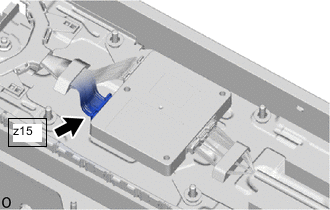
CHECK CONNECTOR CONNECTION CONDITION (BATTERY VOLTAGE SENSOR (for Upper Side) CONNECTOR)
CAUTION:Be sure to wear insulated gloves and protective goggles.
-
Check that the service plug grip is not installed.
Note:After removing the service plug grip, do not turn the power switch on (READY), unless instructed by the repair manual because this may cause a malfunction.
-
Remove the No.1 HV battery protector (for upper side).
-
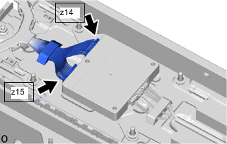
Check the connections of the z14 and z15 battery voltage sensor (for upper side) connector.
OK The connector is connected securely and there are no contact problems. Result Result Proceed to OK A Not connected securely The terminals are not damaged or corroded B Either connector z14 or z15 was not connected securely The terminals are damaged or corroded C
- AClick here
- B
CONNECT SECURELY
- C
REPLACE NO. 1 HV SUPPLY STACK SUB-ASSEMBLYClick here
-
- Click here
CHECK NO. 1 HV SUPPLY STACK SUB-ASSEMBLY (HYBRID BATTERY CELL VOLTAGE)
CAUTION:
-
Be sure to wear insulated gloves and protective goggles.
-
Disconnect only the connector corresponding to the HV battery cell to be checked. Do not disconnect the other connectors.
Note:Make sure to use tester probes with a diameter of approximately 0.5 mm (0.0197 in.) when measuring the voltage of each HV battery cell.
-
Check that the service plug grip is not installed.
Note:After removing the service plug grip, do not turn the power switch on (READY), unless instructed by the repair manual because this may cause a malfunction.
-
Remove the No.1 HV battery protector (for upper side).
-
The value of any of the freeze frame data items "HV battery cell 1 voltage" through "HV battery cell 22 voltage" is 1.6 V or less.
-
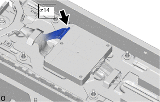
Disconnect the z14 battery voltage sensor (for upper side) connector.
-
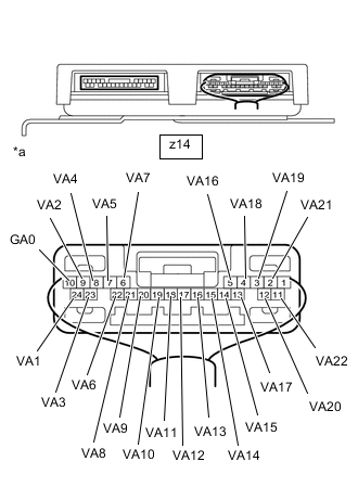
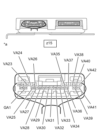
*a Rear view of wire harness connector
(to Battery Voltage Sensor (for Upper Side))
Measure the voltage according to the value(s) in the table below.
Tip:Measure the voltage of the HV battery cells whose value in the freeze frame data was 1.6 V or less only.
Standard Voltage Hybrid Battery Cell Tester Connection Condition 1 z14-10(GA0) - z14-24(VA1) Always 2 z14-24(VA1) - z14-9(VA2) Always 3 z14-9(VA2) - z14-23(VA3) Always 4 z14-23(VA3) - z14-8(VA4) Always 5 z14-8(VA4) - z14-7(VA5) Always 6 z14-7(VA5) - z14-22(VA6) Always 7 z14-22(VA6) - z14-6(VA7) Always 8 z14-6(VA7) - z14-21(VA8) Always 9 z14-21(VA8) - z14-20(VA9) Always 10 z14-20(VA9) - z14-19(VA10) Always 11 z14-19(VA10) - z14-18(VA11) Always 12 z14-18(VA11) - z14-17(VA12) Always 13 z14-17(VA12) - z14-16(VA13) Always 14 z14-16(VA13) - z14-15(VA14) Always 15 z14-15(VA14) - z14-14(VA15) Always 16 z14-14(VA15) - z14-5(VA16) Always 17 z14-5(VA16) - z14-13(VA17) Always 18 z14-13(VA17) - z14-4(VA18) Always 19 z14-4(VA18) - z14-3(VA19) Always 20 z14-3(VA19) - z14-12(VA20) Always 21 z14-12(VA20) - z14-2(VA21) Always 22 z14-2(VA21) - z14-11(VA22) Always CAUTION:Make sure not to cross the electrodes of an electrical tester measurement terminals.
Note:Make sure to check the polarity of each terminal (positive (+) or negative (-)) before connecting a tester.
-
Reconnect the z14 battery voltage sensor (for upper side) connector.
-
-
The value of any of the freeze frame data items "HV battery cell 23 voltage" through "HV battery cell 42 voltage" is 1.6 V or less.
-
Disconnect the z15 battery voltage sensor (for upper side) connector.
-
*a Rear view of wire harness connector
(to Battery Voltage Sensor (for Upper Side))
Measure the voltage according to the value(s) in the table below.
Tip:Measure the voltage of the HV battery cells whose value in the freeze frame data was 1.6 V or less only.
Standard Voltage Hybrid Battery Cell Tester Connection Condition 23 z15-23(GA1) - z15-8(VA23) Always 24 z15-8(VA23) - z15-7(VA24) Always 25 z15-7(VA24) - z15-22(VA25) Always 26 z15-22(VA25) - z15-6(VA26) Always 27 z15-6(VA26) - z15-21(VA27) Always 28 z15-21(VA27) - z15-20(VA28) Always 29 z15-20(VA28) - z15-19(VA29) Always 30 z15-19(VA29) - z15-18(VA30) Always 31 z15-18(VA30) - z15-17(VA31) Always 32 z15-17(VA31) - z15-16(VA32) Always 33 z15-16(VA32) - z15-15(VA33) Always 34 z15-15(VA33) - z15-14(VA34) Always 35 z15-14(VA34) - z15-5(VA35) Always 36 z15-5(VA35) - z15-13(VA36) Always 37 z15-13(VA36) - z15-4(VA37) Always 38 z15-4(VA37) - z15-3(VA38) Always 39 z15-3(VA38) - z15-12(VA39) Always 40 z15-12(VA39) - z15-2(VA40) Always 41 z15-2(VA40) - z15-11(VA41) Always 42 z15-11(VA41) - z15-1(VA42) Always CAUTION:Make sure not to cross the electrodes of an electrical tester measurement terminals.
Note:Make sure to check the polarity of each terminal (positive (+) or negative (-)) before connecting a tester.
-
Reconnect the z15 battery voltage sensor (for upper side) connector.
Result Result Proceed to The voltage between the terminals is 1.6 V or less. A Other than above B -
- AClick here
- B
REPLACE BATTERY VOLTAGE SENSOR (for Upper Side)Click here
-
- Click here
CHECK BATTERY VOLTAGE SENSOR (for Upper Side) (VA1 - VA42)
CAUTION:Be sure to wear insulated gloves and protective goggles.
Note:Make sure to use tester probes with a diameter of approximately 0.5 mm (0.0197 in.) when measuring the resistance.
-
Check that the service plug grip is not installed.
Note:After removing the service plug grip, do not turn the power switch on (READY), unless instructed by the repair manual because this may cause a malfunction.
-
Remove the battery voltage sensor (for upper side).
CAUTION: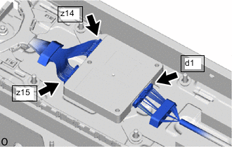
When disconnecting connector d1 of the battery voltage sensor (for upper side), first disconnect connector z14 and z15 from the battery voltage sensor (for upper side).
Note:Insulate each disconnected high-voltage connector with insulating tape. Wrap the connector from the wire harness side to the end of the connector.
-
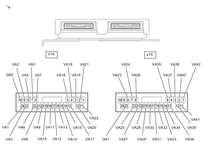
*a Component without harness connected
(Battery Voltage Sensor (for Upper Side))
- - Measure the resistance according to the value(s) in the table below.
Tip:Only inspect the terminals of the battery ECU assembly which correspond to the HV battery cells which measured 1.6 V or less in the previous step.
Standard Resistance Hybrid Battery Cell Tester Connection
(Tester Probe Polarity)
Condition Specified Condition 1 z14-10(GA0) (-) - z14-24(VA1) (+) Always 50 kΩ or more 2 z14-24(VA1) (-) - z14-9(VA2) (+) Always 50 kΩ or more 3 z14-9(VA2) (-) - z14-23(VA3) (+) Always 50 kΩ or more 4 z14-23(VA3) (-) - z14-8(VA4) (+) Always 50 kΩ or more 5 z14-8(VA4) (-) - z14-7(VA5) (+) Always 50 kΩ or more 6 z14-7(VA5) (-) - z14-22(VA6) (+) Always 50 kΩ or more 7 z14-22(VA6) (-) - z14-6(VA7) (+) Always 50 kΩ or more 8 z14-6(VA7) (-) - z14-21(VA8) (+) Always 50 kΩ or more 9 z14-21(VA8) (-) - z14-20(VA9) (+) Always 50 kΩ or more 10 z14-20(VA9) (-) - z14-19(VA10) (+) Always 50 kΩ or more 11 z14-19(VA10) (-) - z14-18(VA11) (+) Always 50 kΩ or more 12 z14-18(VA11) (-) - z14-17(VA12) (+) Always 50 kΩ or more 13 z14-17(VA12) (-) - z14-16(VA13) (+) Always 50 kΩ or more 14 z14-16(VA13) (-) - z14-15(VA14) (+) Always 50 kΩ or more 15 z14-15(VA14) (-) - z14-14(VA15) (+) Always 50 kΩ or more 16 z14-14(VA15) (-) - z14-5(VA16) (+) Always 50 kΩ or more 17 z14-5(VA16) (-) - z14-13(VA17) (+) Always 50 kΩ or more 18 z14-13(VA17) (-) - z14-4(VA18) (+) Always 50 kΩ or more 19 z14-4(VA18) (-) - z14-3(VA19) (+) Always 50 kΩ or more 20 z14-3(VA19) (-) - z14-12(VA20) (+) Always 50 kΩ or more 21 z14-12(VA20) (-) - z14-2(VA21) (+) Always 50 kΩ or more 22 z14-2(VA21) (-) - z14-11(VA22) (+) Always 50 kΩ or more 23 z15-23(GA1) (-) - z15-8(VA23) (+) Always 50 kΩ or more 24 z15-8(VA23) (-) - z15-7(VA24) (+) Always 50 kΩ or more 25 z15-7(VA24) (-) - z15-22(VA25) (+) Always 50 kΩ or more 26 z15-22(VA25) (-) - z15-6(VA26) (+) Always 50 kΩ or more 27 z15-6(VA26) (-) - z15-21(VA27) (+) Always 50 kΩ or more 28 z15-21(VA27) (-) - z15-20(VA28) (+) Always 50 kΩ or more 29 z15-20(VA28) (-) - z15-19(VA29) (+) Always 50 kΩ or more 30 z15-19(VA29) (-) - z15-18(VA30) (+) Always 50 kΩ or more 31 z15-18(VA30) (-) - z15-17(VA31) (+) Always 50 kΩ or more 32 z15-17(VA31) (-) - z15-16(VA32) (+) Always 50 kΩ or more 33 z15-16(VA32) (-) - z15-15(VA33) (+) Always 50 kΩ or more 34 z15-15(VA33) (-) - z15-14(VA34) (+) Always 50 kΩ or more 35 z15-14(VA34) (-) - z15-5(VA35) (+) Always 50 kΩ or more 36 z15-5(VA35) (-) - z15-13(VA36) (+) Always 50 kΩ or more 37 z15-13(VA36) (-) - z15-4(VA37) (+) Always 50 kΩ or more 38 z15-4(VA37) (-) - z15-3(VA38) (+) Always 50 kΩ or more 39 z15-3(VA38) (-) - z15-12(VA39) (+) Always 50 kΩ or more 40 z15-12(VA39) (-) - z15-2(VA40) (+) Always 50 kΩ or more 41 z15-2(VA40) (-) - z15-11(VA41) (+) Always 50 kΩ or more 42 z15-11(VA41) (-) - z15-1(VA42) (+) Always 50 kΩ or more Note:
-
Make sure to check the polarity of each terminal (positive (+) or negative (-)) before connecting a tester.
-
Read the resistance after the value has stabilized.
-
In order to avoid damaging the terminals of the battery voltage sensor, make sure to use tester probes with a diameter of approximately 0.5 mm (0.0197 in.) when measuring the resistance of the battery voltage sensor.
Result Result Proceed to The voltage between the terminals is 50 kΩ or more. A Other than above B -
-
Install the battery voltage sensor (for upper side).
CAUTION:
When connecting connectors z14 and z15 of the battery voltage sensor (for upper Side), first connect connector d1 to the battery voltage sensor (for upper Side).
- A
REPLACE NO. 1 HV SUPPLY STACK SUB-ASSEMBLYClick here
- BClick here
-
- Click here
REPLACE NO. 1 HV SUPPLY STACK SUB-ASSEMBLY
Result Proceed to NEXT
- NEXT
REPLACE BATTERY VOLTAGE SENSOR (for Upper Side)Click here
- NEXT
- Click here
CHECK CONNECTOR CONNECTION CONDITION (BATTERY VOLTAGE SENSOR (for Lower Side) CONNECTOR)
CAUTION:Be sure to wear insulated gloves and protective goggles.
-
Check that the service plug grip is not installed.
Note:After removing the service plug grip, do not turn the power switch on (READY), unless instructed by the repair manual because this may cause a malfunction.
-
Remove the No.1 HV battery protector (for lower side).
-
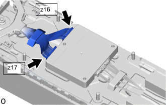
Check the connections of the z16 and z17 battery voltage sensor (for lower side) connector.
OK The connector is connected securely and there are no contact problems. Result Result Proceed to OK A Not connected securely The terminals are not damaged or corroded B Either connector z16 or z17 was not connected securely The terminals are damaged or corroded C
- AClick here
- B
CONNECT SECURELY
- C
REPLACE NO. 2 HV SUPPLY STACK SUB-ASSEMBLYClick here
-
- Click here
CHECK NO. 2 HV SUPPLY STACK SUB-ASSEMBLY (HYBRID BATTERY CELL VOLTAGE)
CAUTION:
-
Be sure to wear insulated gloves and protective goggles.
-
Disconnect only the connector corresponding to the HV battery cell to be checked. Do not disconnect the other connectors.
Note:Make sure to use tester probes with a diameter of approximately 0.5 mm (0.0197 in.) when measuring the voltage of each HV battery cell.
-
Check that the service plug grip is not installed.
Note:After removing the service plug grip, do not turn the power switch on (READY), unless instructed by the repair manual because this may cause a malfunction.
-
Remove the No.1 HV battery protector (for lower side).
-
The value of any of the freeze frame data items "HV battery cell 43 voltage" through "HV battery cell 64 voltage" is 1.6 V or less.
-
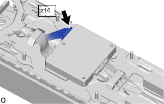
Disconnect the z16 battery voltage sensor (for lower side) connector.
-
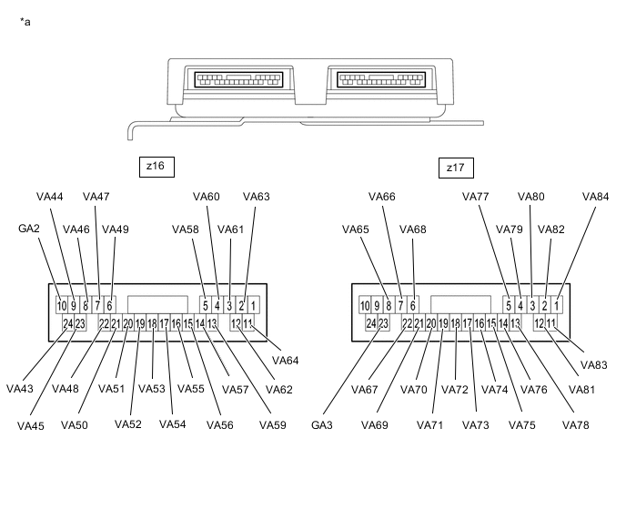
*a Rear view of wire harness connector
(to Battery Voltage Sensor (for Lower Side))
Measure the voltage according to the value(s) in the table below.
Tip:Measure the voltage of the HV battery cells whose value in the freeze frame data was 1.6 V or less only.
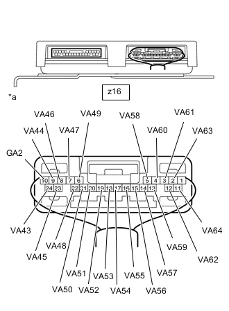
Standard Voltage Hybrid Battery Cell Tester Connection Condition 43 z16-10(GA2) - z16-24(VA43) Always 44 z16-24(VA43) - z16-9(VA44) Always 45 z16-9(VA44) - z16-23(VA45) Always 46 z16-23(VA45) - z16-8(VA46) Always 47 z16-8(VA46) - z16-7(VA47) Always 48 z16-7(VA47) - z16-22(VA48) Always 49 z16-22(VA48) - z16-6(VA49) Always 50 z16-6(VA49) - z16-21(VA50) Always 51 z16-21(VA50) - z16-20(VA51) Always 52 z16-20(VA51) - z16-19(VA52) Always 53 z16-19(VA52) - z16-18(VA53) Always 54 z16-18(VA53) - z16-17(VA54) Always 55 z16-17(VA54) - z16-16(VA55) Always 56 z16-16(VA55) - z16-15(VA56) Always 57 z16-15(VA56) - z16-14(VA57) Always 58 z16-14(VA57) - z16-5(VA58) Always 59 z16-5(VA58) - z16-13(VA59) Always 60 z16-13(VA59) - z16-4(VA60) Always 61 z16-4(VA60) - z16-3(VA61) Always 62 z16-3(VA61) - z16-12(VA62) Always 63 z16-12(VA62) - z16-2(VA63) Always 64 z16-2(VA63) - z16-11(VA64) Always CAUTION:Make sure not to cross the electrodes of an electrical tester measurement terminals.
Note:Make sure to check the polarity of each terminal (positive (+) or negative (-)) before connecting a tester.
-
Reconnect the z16 battery voltage sensor (for lower side) connector.
-
-
The value of any of the freeze frame data items "HV battery cell 65 voltage" through "HV battery cell 84 voltage" is 1.6 V or less.
-
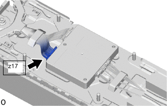
Disconnect the z17 battery voltage sensor (for lower side) connector.
-
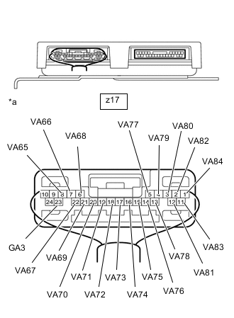
*a Rear view of wire harness connector
(to Battery Voltage Sensor (for Lower Side))
Measure the voltage according to the value(s) in the table below.
Tip:Measure the voltage of the HV battery cells whose value in the freeze frame data was 1.6 V or less only.
Standard Voltage Hybrid Battery Cell Tester Connection Condition 65 z17-23(GA3) - z17-8(VA65) Always 66 z17-8(VA65) - z17-7(VA66) Always 67 z17-7(VA66) - z17-22(VA67) Always 68 z17-22(VA67) - z17-6(VA68) Always 69 z17-6(VA68) - z17-21(VA69) Always 70 z17-21(VA69) - z17-20(VA70) Always 71 z17-20(VA70) - z17-19(VA71) Always 72 z17-19(VA71) - z17-18(VA72) Always 73 z17-18(VA72) - z17-17(VA73) Always 74 z17-17(VA73) - z17-16(VA74) Always 75 z17-16(VA74) - z17-15(VA75) Always 76 z17-15(VA75) - z17-14(VA76) Always 77 z17-14(VA76) - z17-5(VA77) Always 78 z17-5(VA77) - z17-13(VA78) Always 79 z17-13(VA78) - z17-4(VA79) Always 80 z17-4(VA79) - z17-3(VA80) Always 81 z17-3(VA80) - z17-12(VA81) Always 82 z17-12(VA81) - z17-2(VA82) Always 83 z17-2(VA82) - z17-11(VA83) Always 84 z17-11(VA83) - z17-1(VA84) Always CAUTION:Make sure not to cross the electrodes of an electrical tester measurement terminals.
Note:Make sure to check the polarity of each terminal (positive (+) or negative (-)) before connecting a tester.
-
Reconnect the z17 battery voltage sensor (for lower side) connector.
Result Result Proceed to The voltage between the terminals is 1.6 V or less. A Other than above B -
- AClick here
- B
REPLACE BATTERY VOLTAGE SENSOR (for Lower Side)Click here
-
- Click here
CHECK BATTERY VOLTAGE SENSOR (for Lower Side) (VA43 - VA84)
CAUTION:Be sure to wear insulated gloves and protective goggles.
Note:Make sure to use tester probes with a diameter of approximately 0.5 mm (0.0197 in.) when measuring the resistance.
-
Check that the service plug grip is not installed.
Note:After removing the service plug grip, do not turn the power switch on (READY), unless instructed by the repair manual because this may cause a malfunction.
-
Remove the battery voltage sensor (for lower side).
CAUTION: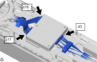
When disconnecting connector d3 of the battery voltage sensor (for lower side), first disconnect connector z16 and z17 from the battery voltage sensor (for lower side).
Note:Insulate each disconnected high-voltage connector with insulating tape. Wrap the connector from the wire harness side to the end of the connector.
-
*a Component without harness connected
(Battery Voltage Sensor (for Lower Side))
- - Measure the resistance according to the value(s) in the table below.
Tip:Only inspect the terminals of the battery ECU assembly which correspond to the HV battery cells which measured 1.6 V or less in the previous step.
Standard Resistance Hybrid Battery Cell Tester Connection
(Tester Probe Polarity)
Condition Specified Condition 43 z16-10(GA2) (-) - z16-24(VA43) (+) Always 50 kΩ or more 44 z16-24(VA43) (-) - z16-9(VA44) (+) Always 50 kΩ or more 45 z16-9(VA44) (-) - z16-23(VA45) (+) Always 50 kΩ or more 46 z16-23(VA45) (-) - z16-8(VA46) (+) Always 50 kΩ or more 47 z16-8(VA46) (-) - z16-7(VA47) (+) Always 50 kΩ or more 48 z16-7(VA47) (-) - z16-22(VA48) (+) Always 50 kΩ or more 49 z16-22(VA48) (-) - z16-6(VA49) (+) Always 50 kΩ or more 50 z16-6(VA49) (-) - z16-21(VA50) (+) Always 50 kΩ or more 51 z16-21(VA50) (-) - z16-20(VA51) (+) Always 50 kΩ or more 52 z16-20(VA51) (-) - z16-19(VA52) (+) Always 50 kΩ or more 53 z16-19(VA52) (-) - z16-18(VA53) (+) Always 50 kΩ or more 54 z16-18(VA53) (-) - z16-17(VA54) (+) Always 50 kΩ or more 55 z16-17(VA54) (-) - z16-16(VA55) (+) Always 50 kΩ or more 56 z16-16(VA55) (-) - z16-15(VA56) (+) Always 50 kΩ or more 57 z16-15(VA56) (-) - z16-14(VA57) (+) Always 50 kΩ or more 58 z16-14(VA57) (-) - z16-5(VA58) (+) Always 50 kΩ or more 59 z16-5(VA58) (-) - z16-13(VA59) (+) Always 50 kΩ or more 60 z16-13(VA59) (-) - z16-4(VA60) (+) Always 50 kΩ or more 61 z16-4(VA60) (-) - z16-3(VA61) (+) Always 50 kΩ or more 62 z16-3(VA61) (-) - z16-12(VA62) (+) Always 50 kΩ or more 63 z16-12(VA62) (-) - z16-2(VA63) (+) Always 50 kΩ or more 64 z16-2(VA63) (-) - z16-11(VA64) (+) Always 50 kΩ or more 65 z17-23(GA3) (-) - z17-8(VA65) (+) Always 50 kΩ or more 66 z17-8(VA65) (-) - z17-7(VA66) (+) Always 50 kΩ or more 67 z17-7(VA66) (-) - z17-22(VA67) (+) Always 50 kΩ or more 68 z17-22(VA67) (-) - z17-6(VA68) (+) Always 50 kΩ or more 69 z17-6(VA68) (-) - z17-21(VA69) (+) Always 50 kΩ or more 70 z17-21(VA69) (-) - z17-20(VA70) (+) Always 50 kΩ or more 71 z17-20(VA70) (-) - z17-19(VA71) (+) Always 50 kΩ or more 72 z17-19(VA71) (-) - z17-18(VA72) (+) Always 50 kΩ or more 73 z17-18(VA72) (-) - z17-17(VA73) (+) Always 50 kΩ or more 74 z17-17(VA73) (-) - z17-16(VA74) (+) Always 50 kΩ or more 75 z17-16(VA74) (-) - z17-15(VA75) (+) Always 50 kΩ or more 76 z17-15(VA75) (-) - z17-14(VA76) (+) Always 50 kΩ or more 77 z17-14(VA76) (-) - z17-5(VA77) (+) Always 50 kΩ or more 78 z17-5(VA77) (-) - z17-13(VA78) (+) Always 50 kΩ or more 79 z17-13(VA78) (-) - z17-4(VA79) (+) Always 50 kΩ or more 80 z17-4(VA79) (-) - z17-3(VA80) (+) Always 50 kΩ or more 81 z17-3(VA80) (-) - z17-12(VA81) (+) Always 50 kΩ or more 82 z17-12(VA81) (-) - z17-2(VA82) (+) Always 50 kΩ or more 83 z17-2(VA82) (-) - z17-11(VA83) (+) Always 50 kΩ or more 84 z17-11(VA83) (-) - z17-1(VA84) (+) Always 50 kΩ or more Note:
-
Make sure to check the polarity of each terminal (positive (+) or negative (-)) before connecting a tester.
-
Read the resistance after the value has stabilized.
-
In order to avoid damaging the terminals of the battery voltage sensor, make sure to use tester probes with a diameter of approximately 0.5 mm (0.0197 in.) when measuring the resistance of the battery voltage sensor.
Result Result Proceed to The voltage between the terminals is 50 kΩ or more. A Other than above B -
-
Install the battery voltage sensor (for lower side).
CAUTION:
When connecting connectors z16 and z17 of the battery voltage sensor (for lower Side), first connect connector d3 to the battery voltage sensor (for lower Side).
- A
REPLACE NO. 2 HV SUPPLY STACK SUB-ASSEMBLYClick here
- BClick here
-
- Click here
REPLACE NO. 2 HV SUPPLY STACK SUB-ASSEMBLY
Result Proceed to NEXT
- NEXT
REPLACE BATTERY VOLTAGE SENSOR (for Lower Side)Click here
- NEXT
- Click here
CLEAR DTC
Result Proceed to NEXT
- NEXTClick here
- Click here
CHECK DTC OUTPUT
-
Connect the GTS to the DLC3.
-
Turn the power switch on (IG) and wait for 1 minutes or more.
-
Enter the following menus: Powertrain / HV Battery / Trouble Codes.
-
Check if DTCs are output.
- Powertrain > HV Battery > Trouble Codes
-
-
Result Result Proceed to "P0E2D00" is not output. A "P0E2D00" is output. B -
Turn the power switch off.
-
- Click here
SIMULATION TEST
Note:Do not turn the power switch off while performing this inspection.
-
With the vehicle stopped and the shift state in Park (P), turn the power switch on (IG) and wait for at least 70 seconds.
-
Turn the power switch on (READY) and without depressing the accelerator pedal, and while depressing the brake pedal, change the shift state to drive (D) and wait for 1 minutes. (Step A)
-
Drive the vehicle 0.5 m (1.6 ft.) forward and perform step A.
-
Drive the vehicle another 0.5 m (1.6 ft.) forward and perform step A. Repeat this procedure 5 times (minimum total driving distance: 2 m (6.6 ft.)).
-
Enter the following menus: Powertrain / Hybrid Control / Trouble Codes.
-
Check if DTCs are output.
- Powertrain > Hybrid Control > Trouble Codes
-
-
Result Result Proceed to "P0AA649" is not output. A "P0AA649" is output. B -
Turn the power switch off.
- AClick here
- B
GO TO DTC CHART (P0AA649)Click here
-
- Click here
CHECK DTC OUTPUT (HV BATTERY)
-
Connect the GTS to the DLC3.
-
Turn the power switch on (IG).
-
Enter the following menus: Powertrain / HV Battery / Trouble Codes.
-
Check for DTCs.
- Powertrain > HV Battery > Trouble Codes
-
-
Result Result Proceed to "P0E2D00" is not output. A "P0E2D00" is output. B -
Turn the power switch off.
- AClick here
GO TO STEP 16
- BClick here
-
- Click here
CHECK INVERTER WITH CONVERTER ASSEMBLY
CAUTION:Be sure to wear insulated gloves.
-
Check that the service plug grip is not installed.
Note:After removing the service plug grip, do not turn the power switch on (READY), unless instructed by the repair manual because this may cause a malfunction.
-
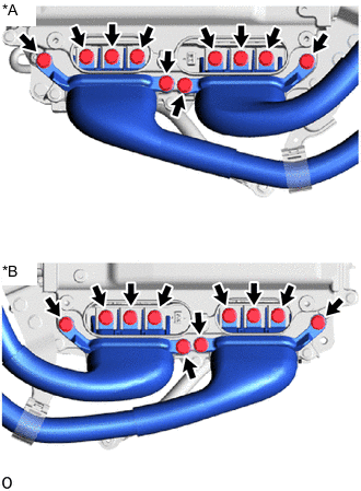
*A for LHD *B for RHD Disconnect the motor cable and generator cable from the inverter with converter assembly.
Tip:Make sure that no foreign matter, coolant or water enters the inverter with converter assembly.
-
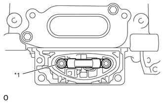
*a High Voltage Terminal Using a megohmmeter set to 500 V, measure the resistance according to the value(s) in the table below.
Note:Be sure to set the megohmmeter to 500 V when performing this test. Using a setting higher than 500 V can result in damage to the component being inspected.
Standard Resistance Tester Connection Condition Specified Condition High voltage terminal - Body ground Power switch off 1 MΩ or more Tip:Perform this inspection with the motor cable and generator cable disconnected from the inverter with converter assembly.
-
Reconnect the motor cable and generator cable from the inverter with converter assembly.
Result Proceed to OK NG
- OKClick here
- NG
REPLACE INVERTER WITH CONVERTER ASSEMBLYClick here
-
- Click here
CHECK HYBRID VEHICLE TRANSMISSION ASSEMBLY (MOTOR CABLE)
CAUTION:Be sure to wear insulated gloves.
-
Check that the service plug grip is not installed.
Note:After removing the service plug grip, do not turn the power switch on (READY), unless instructed by the repair manual because this may cause a malfunction.
-
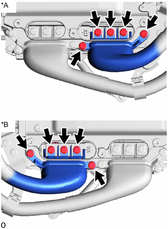
*A for LHD *B for RHD Disconnect the motor cable from the inverter with converter assembly.
Tip:Make sure that no foreign matter, coolant or water enters the inverter with converter assembly.
-
Connect the cable to the negative (-) auxiliary battery terminal.
Tip:As the insulation resistance may vary when motor (MG2) rotates, perform this inspection while rotating the rear wheels.
-
Turn the power switch on (IG).
Note:Turning the power switch on (IG) with the service plug grip removed causes DTCs to be stored. Clear the DTCs after performing this inspection.
-
Move the shift lever to select shift state neutral (N) and lift the vehicle.
-
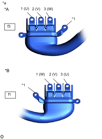
*A for LHD *B for RHD *1 Shield Ground *a Motor Cable
(Inverter with Converter Assembly Side)
Using a megohmmeter set to 500 V, measure the resistance according to the value(s) in the table below while rotating the rear wheels 2 revolutions in the same direction simultaneously.
Note:
-
Carefully perform this inspection as the motor (MG2) may generate current when the rear wheels are rotated by hand.
-
Be sure to set the megohmmeter to 500 V when performing this test. Using a setting higher than 500 V can result in damage to the component being inspected.
Standard Resistance Table 6. for LHD: Tester Connection Condition Specified Condition f3-1 (U) - Body ground and shield ground Power switch on (IG) 100 MΩ or higher f3-2 (V) - Body ground and shield ground Power switch on (IG) 100 MΩ or higher f3-3 (W) - Body ground and shield ground Power switch on (IG) 100 MΩ or higher Table 7. for RHD: Tester Connection Condition Specified Condition f1-3 (U) - Body ground and shield ground Power switch on (IG) 100 MΩ or higher f1-2 (V) - Body ground and shield ground Power switch on (IG) 100 MΩ or higher f1-1 (W) - Body ground and shield ground Power switch on (IG) 100 MΩ or higher -
-
Lower the vehicle and push the P position switch (shift position indicator).
-
Turn the power switch off.
-
Disconnect the cable from the negative (-) auxiliary battery terminal.
Result Proceed to OK NG
- OKClick here
- NGClick here
-
- Click here
CHECK HYBRID VEHICLE TRANSMISSION ASSEMBLY (GENERATOR CABLE)
CAUTION:Be sure to wear insulated gloves.
-
Check that the service plug grip is not installed.
Note:After removing the service plug grip, do not turn the power switch on (READY), unless instructed by the repair manual because this may cause a malfunction.
-
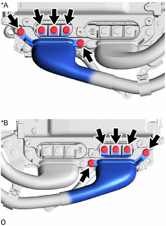
*A for LHD *B for RHD Disconnect the generator cable from the inverter with converter assembly.
Tip:Make sure that no foreign matter, coolant or water enters the inverter with converter assembly.
-
Connect the cable to the negative (-) auxiliary battery terminal.
Tip:As the insulation resistance may vary when generator (MG1) rotates, perform this inspection while rotating the rear wheels.
-
Turn the power switch on (IG).
Note:Turning the power switch on (IG) with the service plug grip removed causes DTCs to be stored. Clear the DTCs after performing this inspection.
-
Move the shift lever to select shift state neutral (N) and lift the vehicle.
-
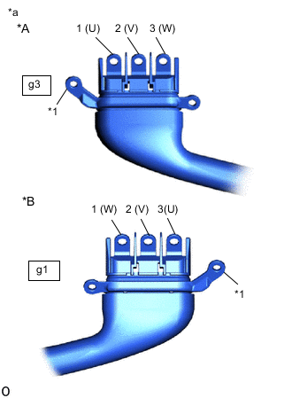
*A for LHD *B for RHD *1 Shield Ground *a Generator Cable
(Inverter with Converter Assembly Side)
Using a megohmmeter set to 500 V, measure the resistance according to the value(s) in the table below while rotating the rear wheels 2 revolutions in the same direction simultaneously.
Note:
-
Carefully perform this inspection as the generator (MG1) may generate current when the rear wheels are rotated by hand.
-
Be sure to set the megohmmeter to 500 V when performing this test. Using a setting higher than 500 V can result in damage to the component being inspected.
Standard Resistance Table 8. for LHD: Tester Connection Condition Specified Condition g3-1 (U) - Body ground and shield ground Power switch on (IG) 100 MΩ or higher g3-2 (V) - Body ground and shield ground Power switch on (IG) 100 MΩ or higher g3-3 (W) - Body ground and shield ground Power switch on (IG) 100 MΩ or higher Table 9. for RHD: Tester Connection Condition Specified Condition g1-3 (U) - Body ground and shield ground Power switch on (IG) 100 MΩ or higher g1-2 (V) - Body ground and shield ground Power switch on (IG) 100 MΩ or higher g1-1 (W) - Body ground and shield ground Power switch on (IG) 100 MΩ or higher -
-
Lower the vehicle and push the P position switch (shift position indicator).
-
Turn the power switch off.
-
Disconnect the cable from the negative (-) auxiliary battery terminal.
Result Proceed to OK NG
- OKClick here
GO TO STEP 20
- NGClick here
-
- Click here
CHECK MOTOR CABLE
CAUTION:Be sure to wear insulated gloves.
-
Check that the service plug grip is not installed.
Note:After removing the service plug grip, do not turn the power switch on (READY), unless instructed by the repair manual because this may cause a malfunction.
-
Remove the motor cable from the hybrid vehicle transmission assembly.
for 2WD:
for AWD:
-
*A for LHD *B for RHD *1 Shield Ground *a Motor Cable
(Inverter with Converter Assembly Side)
Using a megohmmeter set to 500 V, measure the resistance according to the value(s) in the table below.
Note:Be sure to set the megohmmeter to 500 V when performing this test. Using a setting higher than 500 V can result in damage to the component being inspected.
Standard Resistance Table 10. for LHD: Tester Connection Condition Specified Condition f3-1 (U) - Body ground and shield ground Power switch off 100 MΩ or higher f3-2 (V) - Body ground and shield ground Power switch off 100 MΩ or higher f3-3 (W) - Body ground and shield ground Power switch off 100 MΩ or higher Table 11. for RHD: Tester Connection Condition Specified Condition f1-3 (U) - Body ground and shield ground Power switch off 100 MΩ or higher f1-2 (V) - Body ground and shield ground Power switch off 100 MΩ or higher f1-1 (W) - Body ground and shield ground Power switch off 100 MΩ or higher Result Proceed to OK NG
- OK
REPLACE HYBRID VEHICLE TRANSMISSION ASSEMBLY for 2WD:
REPLACE HYBRID VEHICLE TRANSMISSION ASSEMBLYClick here
REPLACE HYBRID VEHICLE TRANSMISSION ASSEMBLY for AWD:
REPLACE HYBRID VEHICLE TRANSMISSION ASSEMBLYClick here
- NG
REPLACE MOTOR CABLEClick here
-
- Click here
CHECK GENERATOR CABLE
CAUTION:Be sure to wear insulated gloves.
-
Check that the service plug grip is not installed.
Note:After removing the service plug grip, do not turn the power switch on (READY), unless instructed by the repair manual because this may cause a malfunction.
-
Remove the generator cable from the hybrid vehicle transmission assembly.
for 2WD:
for AWD:
-
*A for LHD *B for RHD *1 Shield Ground *a Generator Cable
(Inverter with Converter Assembly Side)
Using a megohmmeter set to 500 V, measure the resistance according to the value(s) in the table below.
Note:Be sure to set the megohmmeter to 500 V when performing this test. Using a setting higher than 500 V can result in damage to the component being inspected.
Standard Resistance Table 12. for LHD: Tester Connection Condition Specified Condition g3-1 (U) - Body ground and shield ground Power switch off 100 MΩ or higher g3-2 (V) - Body ground and shield ground Power switch off 100 MΩ or higher g3-3 (W) - Body ground and shield ground Power switch off 100 MΩ or higher Table 13. for RHD: Tester Connection Condition Specified Condition g1-3 (U) - Body ground and shield ground Power switch off 100 MΩ or higher g1-2 (V) - Body ground and shield ground Power switch off 100 MΩ or higher g1-1 (W) - Body ground and shield ground Power switch off 100 MΩ or higher Result Proceed to OK NG
- OK
REPLACE HYBRID VEHICLE TRANSMISSION ASSEMBLY for 2WD:
REPLACE HYBRID VEHICLE TRANSMISSION ASSEMBLYClick here
REPLACE HYBRID VEHICLE TRANSMISSION ASSEMBLY for AWD:
REPLACE HYBRID VEHICLE TRANSMISSION ASSEMBLYClick here
- NG
REPLACE GENERATOR CABLEClick here
-
- Click here
CHECK CONNECTOR CONNECTION CONDITION (BATTERY VOLTAGE SENSOR (for Upper Side) CONNECTOR)
CAUTION:Be sure to wear insulated gloves and protective goggles.
-
Check that the service plug grip is not installed.
Note:After removing the service plug grip, do not turn the power switch on (READY), unless instructed by the repair manual because this may cause a malfunction.
-
Remove the No.1 HV battery protector (for upper side).
-

Check the connections of the z14 and z15 battery voltage sensor (for upper side) connector.
OK The connector is connected securely and there are no contact problems. Result Result Proceed to OK A Not connected securely The terminals are not damaged or corroded B Either connector z14 or z15 was not connected securely The terminals are damaged or corroded C
- AClick here
- B
CONNECT SECURELY
- C
REPLACE NO. 1 HV SUPPLY STACK SUB-ASSEMBLYClick here
-
- Click here
CHECK CONNECTOR CONNECTION CONDITION (BATTERY VOLTAGE SENSOR (for Lower Side) CONNECTOR)
CAUTION:Be sure to wear insulated gloves and protective goggles.
-
Check that the service plug grip is not installed.
Note:After removing the service plug grip, do not turn the power switch on (READY), unless instructed by the repair manual because this may cause a malfunction.
-
Remove the No.1 HV battery protector (for lower side).
-

Check the connections of the z16 and z17 battery voltage sensor (for lower side) connector.
OK The connector is connected securely and there are no contact problems. Result Result Proceed to OK A Not connected securely The terminals are not damaged or corroded B Either connector z16 or z17 was not connected securely The terminals are damaged or corroded C
- AClick here
- B
CONNECT SECURELY
- C
REPLACE NO. 2 HV SUPPLY STACK SUB-ASSEMBLYClick here
-
- Click here
CHECK HARNESS AND CONNECTOR (BATTERY ECU ASSEMBLY - BATTERY VOLTAGE SENSOR)
CAUTION:Be sure to wear insulated gloves and protective goggles.
Note:Make sure to use tester probes with a diameter of approximately 0.5 mm (0.0197 in.) when measuring the voltage of each HV battery cell.
-
Check that the service plug grip is not installed.
Note:After removing the service plug grip, do not turn the power switch on (READY), unless instructed by the repair manual because this may cause a malfunction.
-
Remove the No.1 HV battery protector (for upper side).
-
Disconnect the d1 battery voltage sensor (for upper side) connector.
CAUTION:
When disconnecting connector d1 of the battery voltage sensor (for upper side), first disconnect connector z14 and z15 from the battery voltage sensor (for upper side).
Note:Insulate each disconnected high-voltage connector with insulating tape. Wrap the connector from the wire harness side to the end of the connector.
-
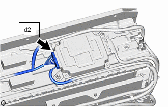
Disconnect the d2 battery ECU assembly connector.
Note:
-
Insulate each disconnected high-voltage connector with insulating tape. Wrap the connector from the wire harness side to the end of the connector.
-
Before disconnecting the connector, check that it is not loose or disconnected.
-
-
Remove the No.1 HV battery protector (for lower side).
-
Disconnect the d3 battery voltage sensor (for lower side) connector.
CAUTION:
When disconnecting connector d3 of the battery voltage sensor (for lower side), first disconnect connector z16 and z17 from the battery voltage sensor (for lower side).
Note:Insulate each disconnected high-voltage connector with insulating tape. Wrap the connector from the wire harness side to the end of the connector.
-
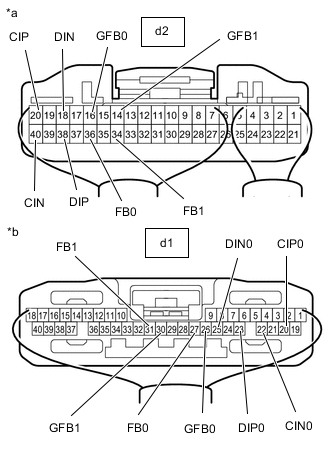
*a Component without harness connected
(to Battery ECU Assembly)
*b Component without harness connected
(to Battery Voltage Sensor (for Upper Side))
Measure the resistance according to the value(s) in the table below.
Standard Resistance Tester Connection Condition Specified Condition d2-18(DIN) - d1-25(DIN0) Always Below 1 Ω d2-38(DIP) - d1-23(DIP0) Always Below 1 Ω d2-40(CIN) - d1-22(CIN0) Always Below 1 Ω d2-20(CIP) - d1-20(CIP0) Always Below 1 Ω d2-16(GFB0) - d1-26(GFB0) Always Below 1 Ω d2-36(FB0) - d1-27(FB0) Always Below 1 Ω d2-14(GFB1) - d1-30(GFB1) Always Below 1 Ω d2-34(FB1) - d1-31(FB1) Always Below 1 Ω -
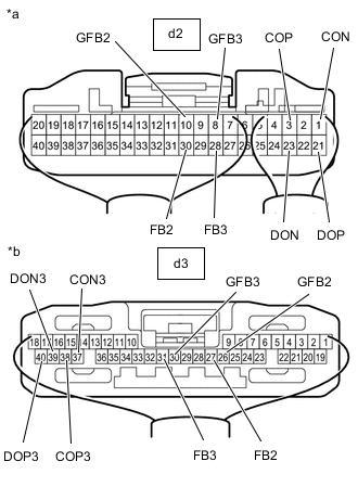
*a Component without harness connected
(to Battery ECU Assembly)
*b Component without harness connected
(to Battery Voltage Sensor (for Lower Side))
Measure the resistance according to the value(s) in the table below.
Standard Resistance Tester Connection Condition Specified Condition d2-1(CON) - d3-37(CON3) Always Below 1 Ω d2-3(COP) - d3-38(COP3) Always Below 1 Ω d2-23(DON) - d3-39(DON3) Always Below 1 Ω d2-21(DOP) - d3-40(DOP3) Always Below 1 Ω d2-10(GFB2) - d3-26(GFB2) Always Below 1 Ω d2-30(FB2) - d3-27(FB2) Always Below 1 Ω d2-8(GFB3) - d3-30(GFB3) Always Below 1 Ω d2-28(FB3) - d3-31(FB3) Always Below 1 Ω -
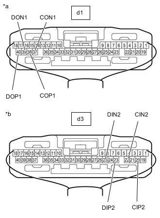
*a Component without harness connected
(to Battery Voltage Sensor (for Upper Side))
*b Component without harness connected
(to Battery Voltage Sensor (for Lower Side))
Measure the resistance according to the value(s) in the table below.
Standard Resistance Tester Connection Condition Specified Condition d1-37(CON1) - d3-22(CIN2) Always Below 1 Ω d1-38(COP1) - d3-20(CIP2) Always Below 1 Ω d1-39(DON1) - d3-25(DIN2) Always Below 1 Ω d1-40(DOP1) - d3-23(DIP2) Always Below 1 Ω -
Install the battery voltage sensor (for lower side).
CAUTION:
When connecting connectors z16 and z17 of the battery voltage sensor (for lower Side), first connect connector d3 to the battery voltage sensor (for lower Side).
-
Reconnect the d2 battery ECU assembly connector.
-
Install the battery voltage sensor (for upper side).
CAUTION:
When connecting connectors z14 and z15 of the battery voltage sensor (for upper Side), first connect connector d1 to the battery voltage sensor (for upper Side).
Result Proceed to OK NG
- OK
REPLACE BATTERY VOLTAGE SENSOR (for Upper Side), BATTERY VOLTAGE SENSOR (for Lower Side) and BATTERY ECU ASSEMBLYClick here
- NG
REPAIR OR REPLACE HARNESS OR CONNECTOR
-