ENGINE ASSEMBLY REMOVAL
CAUTION / NOTICE / HINT
The necessary procedures (adjustment, calibration, initialization, or registration) that must be performed after parts are removed, installed, or replaced during the engine assembly removal/installation are shown below.
| Replaced Part or Performed Procedure | Necessary Procedure | Effect/Inoperative Function when Necessary Procedure not Performed | Link |
|---|---|---|---|
| Battery terminal is disconnected/reconnected | Drive the vehicle until stop and start control is permitted (approximately 5 to 60 minutes) | Stop and start system | |
| Memorize steering angle neutral point | LKA/LDA system | ||
| Parking support brake system*1 | |||
| Pre-collision system | |||
| Adaptive high beam system | |||
Lighting system (EXT) |
|||
| Variable gear ratio steering system | |||
| Parking assist monitor system | |||
| Panoramic view monitor system | |||
| Initialize rear door sunshade system | Rear door sunshade system | ||
| Initialize power trunk lid system | Power trunk lid system | ||
|
Inspection after repairs |
|
w/ Canister Pump Module: w/o Canister Pump Module: |
| Piston ring | Inspection after repair |
|
|
Heavy Knock History |
- | ||
| Front exhaust pipe assembly*3 | GPF deposition value clear |
|
|
| Replacement of engine assembly | Inspection after repair |
|
w/ Canister Pump Module: w/o Canister Pump Module: |
|
|
for AGA0E: for AGA0F: |
|
| ECM | Vehicle Identification Number (VIN) registration | DTC P063051 is output | w/ Canister Pump Module: w/o Canister Pump Module: |
Heavy Knock History |
- | ||
for AGA0E: |
|
|
for Initialization: for Registration: |
for AGA0E: |
ATF thermal degradation estimate reset | The value of the Data List item "ATF Thermal Degradation Estimate" is not estimated correctly. | |
for AGA0F: |
|
|
for Initialization: for Registration: |
for AGA0F: |
ATF thermal degradation estimate reset | The value of the Data List item "ATF Thermal Degradation Estimate" is not estimated correctly. | |
| Parts between the steering wheel and tires have been removed/installed, replaced or adjusted | Perform Actuator Angle Neutral Point Calibration and Initialization |
|
|
| Front bumper assembly (Including removal and installation) |
|
Parking support brake system | |
| Front television camera view adjustment | Panoramic view monitor system | ||
| Suspension, tires, etc |
|
Parking support brake system | |
|
Panoramic view monitor system | ||
| Rear television camera assembly optical axis (Back camera position setting) | Parking assist monitor system |
Click here Click here
*2: Set the transmission compensation code for the new automatic transmission.
*3: w/ Gasoline Particulate Filter
CAUTION:
-
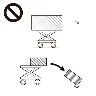
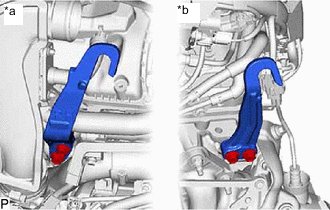
*a An Object Exceeding Weight Limit of Engine Lifter The engine assembly with transaxle is very heavy. Be sure to follow the procedure described in the repair manual, or the engine lifter may suddenly drop or the engine assembly with transaxle may fall off the engine lifter.
-
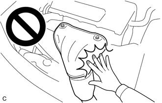
To prevent burns, do not touch the engine, exhaust manifold or other high temperature components while the engine is hot.
PROCEDURE
-
PRECAUTION
Note
After turning the engine switch off, waiting time may be required before disconnecting the cable from the battery terminal. Therefore, make sure to read the disconnecting the cable from the battery terminal notice before proceeding with work.
-
AIR SUSPENSION CONTROL PROHIBITED (w/ Air Suspension)
-
REMOVE LUGGAGE COMPARTMENT MAT SUB-ASSEMBLY
-
REMOVE TOOL BOX
-
DISCHARGE FUEL SYSTEM PRESSURE
-
DISCONNECT CABLE FROM NEGATIVE BATTERY TERMINAL
Note
When disconnecting the cable, some systems need to be initialized after the cable is reconnected.
-
PARKING LOCK FORCED RELEASE
-
for 2WD:
-
for AWD:
-
-
REMOVE UPPER RADIATOR SUPPORT SEAL
-
Remove the 7 clips and upper radiator support seal.
-
-
REMOVE RADIATOR COVER PLATE
-
Remove the 7 clips and radiator cover plate.
-
-
REMOVE LOWER RADIATOR AIR DEFLECTOR
-
Remove the 6 clips and lower radiator air deflector.
-
-
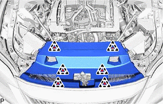
REMOVE V-BANK COVER SUB-ASSEMBLY
-
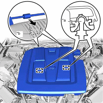
*a Pin *b Hook Raise the front of the V-bank cover sub-assembly to detach the 2 pins. Then remove the 2 V-bank cover hooks from the bracket, and remove the V-bank cover sub-assembly.
-
-
RECOVER REFRIGERANT FROM REFRIGERATION SYSTEM
-
for HFC-134a (R134a):
-
for HFO-1234yf (R1234yf):
-
-
PLACE FRONT WHEELS FACING STRAIGHT AHEAD
-
REMOVE FRONT WHEEL
-
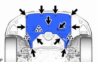
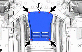
REMOVE NO. 1 ENGINE UNDER COVER ASSEMBLY (for 2WD)
-
Remove the 15 screws, 3 clips and No. 1 engine under cover assembly.
-
-
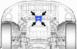
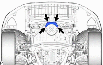
REMOVE TRANSMISSION UNDER COVER (for 2WD)
-

Screw 
Bolt Remove the 2 bolts, 2 screws and transmission under cover.
-
-
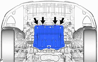
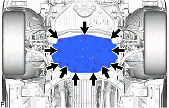
REMOVE NO. 2 ENGINE UNDER COVER ASSEMBLY (for 2WD)
-
Remove the 10 bolts, clip and No. 2 engine under cover assembly.
-
-
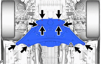
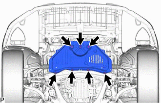
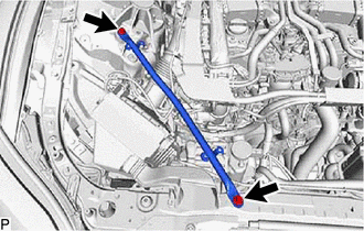
REMOVE FRONT SUSPENSION MEMBER BRACE (for 2WD)
-
Remove the 4 bolts and front suspension member brace.
-
-
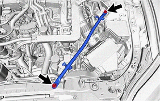
REMOVE STRUT BAR BRACKET SUPPORT SUB-ASSEMBLY (for 2WD)
-
Remove the 4 bolts and strut bar bracket support sub-assembly.
-
-
REMOVE NO. 1 ENGINE UNDER COVER ASSEMBLY (for AWD)
-
Remove the 12 screws, 3 clips and No. 1 engine under cover assembly.
-
-
REMOVE TRANSMISSION UNDER COVER (for AWD)
-
Screw Bolt Remove the 4 bolts, screw and transmission under cover.
-
-
REMOVE NO. 2 ENGINE UNDER COVER ASSEMBLY (for AWD)
-
Remove the 11 bolts, and No. 2 engine under cover assembly.
-
-
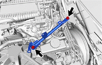
REMOVE FRONT SUSPENSION MEMBER BRACE (for AWD)
-
Remove the 4 bolts and front suspension member brace.
-
-
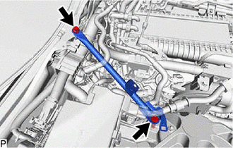
REMOVE STRUT BAR BRACKET SUPPORT SUB-ASSEMBLY (for AWD)
-
Remove the 7 bolts and strut bar bracket support sub-assembly.
-
-
DRAIN ENGINE OIL
-
DRAIN ENGINE COOLANT
-
DRAIN COOLANT (for Intercooler)
-
DRAIN AUTOMATIC TRANSMISSION FLUID
-
for 2WD:
-
for AWD:
-
-
DRAIN DIFFERENTIAL OIL (for AWD)
-
REMOVE FRONT WIPER ARM HEAD CAP
-
REMOVE FRONT WIPER ARM AND BLADE ASSEMBLY LH
-
REMOVE FRONT WIPER ARM AND BLADE ASSEMBLY RH
-
REMOVE FRONT FENDER REINFORCEMENT SUB-ASSEMBLY TOP LH
-
REMOVE HOOD TO COWL TOP SEAL
-
REMOVE COWL TOP VENTILATOR LOUVER REINFORCEMENT
-
REMOVE CENTER NO. 2 COWL TOP VENTILATOR LOUVER
-
REMOVE CENTER COWL TOP VENTILATOR LOUVER
-
REMOVE COWL TOP VENTILATOR LOUVER SUB-ASSEMBLY
-
REMOVE RADIATOR SUPPORT TO CROSSMEMBER BRACE SUB-ASSEMBLY LH
-
Remove the 2 bolts and radiator support to crossmember brace sub-assembly LH.
-
-
REMOVE RADIATOR SUPPORT TO CROSSMEMBER BRACE SUB-ASSEMBLY RH
-
Remove the 2 bolts and radiator support to crossmember brace sub-assembly RH.
-
-
REMOVE FENDER APRON BRACE SUB-ASSEMBLY LH
-
Remove the 2 bolts and fender apron brace sub-assembly LH.
-
-
REMOVE FENDER APRON BRACE SUB-ASSEMBLY RH
-
Remove the 2 bolts and fender apron brace sub-assembly RH.
-
-
REMOVE AIR CLEANER ASSEMBLY LH
-
Disconnect the mass air flow meter sub-assembly connector.
-
Detach the clamp and disconnect the wire harness clamp from the air cleaner assembly LH.
-
Disconnect the vacuum hose sub-assembly.
-
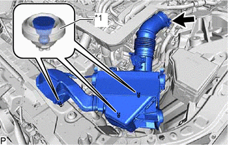
*1 Air Cleaner Support Pull out the 3 air cleaner assembly LH pins from the air cleaner support bracket and radiator upper support.
-
Loosen the hose clamp and remove the air cleaner assembly LH.
-
-
REMOVE AIR CLEANER ASSEMBLY RH
-
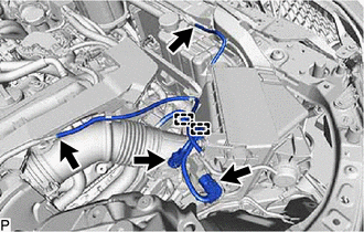
Disconnect the mass air flow meter sub-assembly connector.
-
Disconnect the vacuum switching valve assembly connector.
-
Detach the 2 clamps and disconnect the wire harness clamp from the air cleaner assembly RH.
-
Disconnect the 2 vacuum hose sub-assemblies.
-
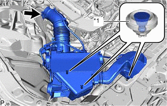
*1 Air Cleaner Support Pull out the 3 air cleaner assembly RH pins from the air cleaner support bracket and radiator upper support.
-
Loosen the hose clamp and remove the air cleaner assembly RH.
-
-
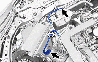
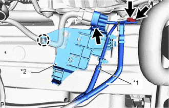
DISCONNECT NO. 1 FUEL VAPOR FEED HOSE
-
Slide the clip and disconnect the No. 1 fuel vapor feed hose from the fuel vapor feed pipe.
-
-
REMOVE RADIATOR RESERVE TANK ASSEMBLY
-
REMOVE INTERCOOLER RESERVE TANK ASSEMBLY
-
REMOVE HEATER ACCESSORY ASSEMBLY (w/ Stop And Start System)
-
for 2WD:
-
for AWD:
-
-
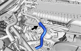
DISCONNECT NO. 3 RADIATOR HOSE
-
DISCONNECT NO. 4 RADIATOR HOSE
-
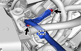
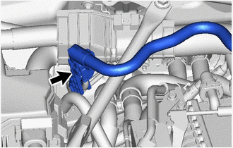
DISCONNECT INLET HEATER WATER HOSE
-
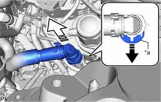
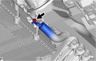
*a Retainer Release the retainer and disconnect the inlet heater water hose from the No. 1 water by-pass pipe as shown in the illustration.
-
-
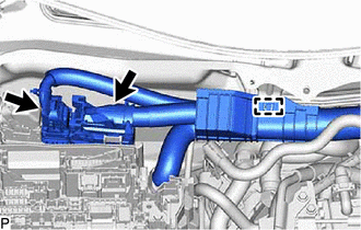
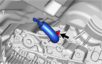
DISCONNECT OUTLET HEATER WATER HOSE
-
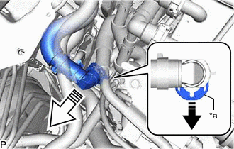
*a Retainer Release the retainer and disconnect the outlet heater water hose from the heater outlet pipe as shown in the illustration.
-
-
DISCONNECT NO. 1 VACUUM HOSE CONNECTOR
-
REMOVE NO. 1 OIL COOLER OUTLET HOSE (w/ In-tank Oil Cooler)
-
for 2WD:
-
for AWD:
-
-
REMOVE WATER INLET HOSE (w/ In-tank Oil Cooler)
-
for 2WD:
-
for AWD:
-
-
REMOVE NO. 1 TRANSMISSION OIL COOLER HOSE (w/ In-tank Oil Cooler)
-
for 2WD:
-
for AWD:
-
-
REMOVE NO. 1 OIL COOLER INLET HOSE (w/ In-tank Oil Cooler)
-
for 2WD:
-
for AWD:
-
-
REMOVE NO. 1 WATER BY-PASS HOSE (w/ In-tank Oil Cooler)
-
for 2WD:
-
for AWD:
-
-
REMOVE WATER INLET HOSE (w/o In-tank Oil Cooler)
-
for 2WD:
-
for AWD:
-
-
REMOVE NO. 1 OIL COOLER OUTLET HOSE (w/o In-tank Oil Cooler)
-
for 2WD:
-
for AWD:
-
-
REMOVE NO. 1 OIL COOLER INLET HOSE (w/o In-tank Oil Cooler)
-
for 2WD:
-
for AWD:
-
-
REMOVE NO. 1 WATER BY-PASS HOSE (w/o In-tank Oil Cooler)
-
for 2WD:
-
for AWD:
-
-
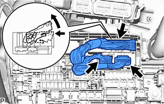
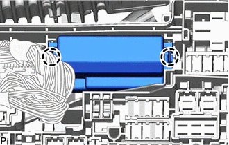
DISCONNECT NO. 2 ENGINE WIRE (for LHD)
Tech Tips
After disconnecting the wire harness, secure it with tape or equivalent to keep it out of the way.
-
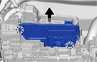
Remove the upper relay block cover from the No. 1 engine room relay block.
-
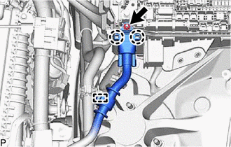
Detach the clamp.
-
Remove the bolt.
-
Detach the 2 claws and disconnect the No. 2 engine wire from the No. 1 engine room relay block.
-
-
DISCONNECT NO. 2 ENGINE WIRE (for RHD)
Tech Tips
After disconnecting the wire harness, secure it with tape or equivalent to keep it out of the way.
-
Remove the upper relay block cover from the No. 1 engine room relay block.
-
Detach the clamp.
-
Remove the bolt.
-
Detach the 2 claws and disconnect the No. 2 engine wire from the No. 1 engine room relay block.
-
-
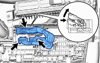
DISCONNECT ENGINE WIRE (for LHD)
Tech Tips
After disconnecting the wire harness, secure it with tape or equivalent to keep it out of the way.
-
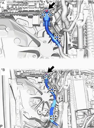
*A for 2WD *B for AWD for 2WD:
-
Detach the clamp.
-
-
for AWD:
-
Detach the 2 clamps.
-
-
Remove the nut.
-
Detach the 2 claws and disconnect the engine wire from the No. 1 engine room relay block.
-
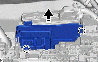
Disconnect the 2 ECM connectors.
-
Detach the clamp.
-
Detach the 2 claws and disconnect the No. 1 semiconductor power integration ECU from the No. 1 engine room relay block.
-
Disconnect the 2 connectors.
-
Detach the claw and disconnect the junction connector.
-

Disconnect in this Direction Detach the 2 claws and disconnect the connector holder from the No. 1 engine room relay block.
-
-
DISCONNECT ENGINE WIRE (for RHD)
Tech Tips
After disconnecting the wire harness, secure it with tape or equivalent to keep it out of the way.
-
Detach the clamp.
-
Remove the nut.
-
Detach the 2 claws and disconnect the engine wire from the No. 1 engine room relay block.
-
Disconnect the 2 ECM connectors.
-
Detach the clamp.
-
Detach the 2 claws and disconnect the No. 1 semiconductor power integration ECU from the No. 1 engine room relay block.
-
Disconnect the 2 connectors.
-
Detach the claw and disconnect the junction connector.
-
Detach the 2 claws and disconnect the connector holder from the No. 1 engine room relay block.
-
-
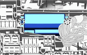
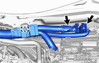
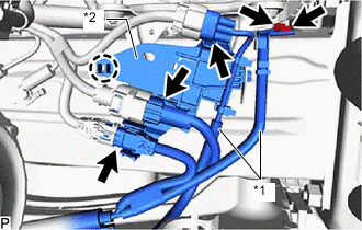
DISCONNECT NO. 3 ENGINE ROOM WIRE (for LHD)
Tech Tips
After disconnecting the wire harness, secure it with tape or equivalent to keep it out of the way.
-
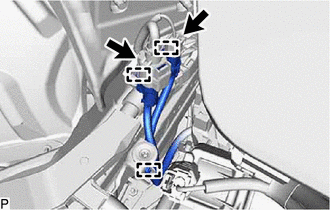
RH Side:
-
Disconnect the 2 connectors.
-
Detach the 3 clamps and disconnect the No. 3 engine room wire.
-
-
*1 No. 3 Engine Room Wire *2 No. 10 Connector Holder LH Side:
-
Disconnect the connector.
-
Detach the claw and disconnect the No. 10 connector holder.
-
Remove the 2 bolts and disconnect the No. 3 engine room wire.
-
-
-
DISCONNECT NO. 3 ENGINE ROOM WIRE (for RHD)
Tech Tips
After disconnecting the wire harness, secure it with tape or equivalent to keep it out of the way.
-
*1 No. 3 Engine Room Wire *2 No. 10 Connector Holder Disconnect the connector.
-
Detach the claw and disconnect the No. 10 connector holder.
-
Remove the 2 bolts and disconnect the No. 3 engine room wire.
-
-
DISCONNECT NO. 3 ENGINE WIRE
Tech Tips
After disconnecting the wire harness, secure it with tape or equivalent to keep it out of the way.
-
Detach the clamp.
-
Remove the 2 bolts and disconnect the No. 3 engine wire from the timing chain or belt cover sub-assembly and wire harness clamp bracket.
-
-
REMOVE AIR CLEANER SUPPORT BRACKET
-
Remove the 2 bolts and air cleaner support bracket.
-
-
DISCONNECT DISCHARGE HOSE SUB-ASSEMBLY
-
for 2WD:
-
for AWD:
-
-
DISCONNECT SUCTION HOSE SUB-ASSEMBLY
-
for 2WD:
-
for AWD:
-
-
DISCONNECT FUEL TUBE SUB-ASSEMBLY
-
Disconnect the fuel tube sub-assembly.
-
-
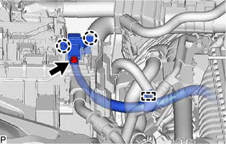
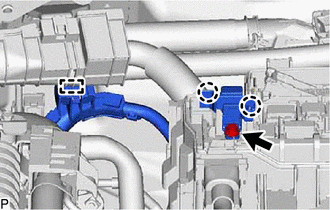
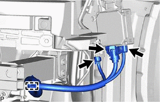
DISCONNECT INTERCOOLER COOLING WATER INLET HOSE AND INTERCOOLER COOLING WATER OUTLET HOSE
-
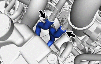
Slide the clips and disconnect the intercooler cooling water inlet hose and intercooler cooling water outlet hose from the No. 1 water by-pass tube.
-
-
REMOVE FRONT BUMPER COVER
-
for Sport Package:
-
except Sport Package:
-
-
REMOVE NO. 2 FRONT BUMPER REINFORCEMENT SUB-ASSEMBLY
-
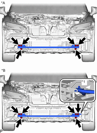
*A w/o Active Stabilizer System *B w/ Active Stabilizer System *1 Bracket w/o Active Stabilizer System:
-
Remove the 6 nuts and No. 2 front bumper reinforcement sub-assembly.
-
-
w/ Active Stabilizer System:
-
Remove the 6 nuts, bracket and No. 2 front bumper reinforcement sub-assembly.
-
-
-
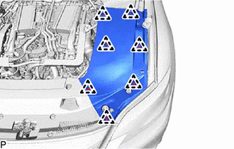
REMOVE RADIATOR SUPPORT EXTENSION LH
-
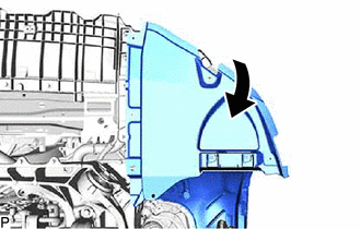
Open a part of the front fender liner LH as shown in the illustration.
-
Remove the 3 bolts, detach the 2 claws and remove the radiator support extension LH from the radiator support opening cover.
-
-
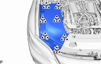
REMOVE RADIATOR SUPPORT EXTENSION RH
-
Open a part of the front fender liner RH as shown in the illustration.
-
Remove the 3 bolts, detach the 2 claws and remove the radiator support extension RH from the radiator support opening cover.
-
-
REMOVE RADIATOR SUPPORT OPENING COVER
-
Remove the 4 bolts, detach the 3 claws and remove the radiator support opening cover from the front crossmember sub-assembly.
-
-
DISCONNECT FRONT ACTIVE STABILIZER CONTROL ECU CONNECTOR (w/ Active Stabilizer System)
-
Detach the clamp and disconnect the 3 connectors.
-
-
REMOVE REAR FRAME RAIL SUB-ASSEMBLY LH
-
for 2WD:
-
Remove the 3 bolts, 2 nuts and rear frame rail sub-assembly LH.
-
-
for AWD:
-
Remove the 3 bolts and rear frame rail sub-assembly LH.
-
-
-
REMOVE REAR FRAME RAIL SUB-ASSEMBLY RH
-
for 2WD:
-
Remove the 3 bolts, 2 nuts and rear frame rail sub-assembly RH.
-
-
for AWD:
-
Remove the 3 bolts and rear frame rail sub-assembly RH.
-
-
-
REMOVE REAR FLOOR SIDE MEMBER COVER LH
-
REMOVE REAR FLOOR SIDE MEMBER COVER RH
-
REMOVE NO. 2 FLOOR BOARD SUB-ASSEMBLY
-
REMOVE FLOOR BOARD SUB-ASSEMBLY
-
REMOVE NO. 3 EXHAUST PIPE SUPPORT BRACKET
-
REMOVE FRONT CENTER FLOOR BRACE SUB-ASSEMBLY
-
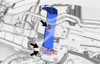
INSTALL SST WITH FRONT EXHAUST PIPE ASSEMBLY
-
REMOVE FRONT EXHAUST PIPE ASSEMBLY
-
REMOVE NO. 1 CENTER FLOOR HEAT INSULATOR SUB-ASSEMBLY
-
REMOVE NO. 2 FUEL TANK PROTECTOR
-
REMOVE PROPELLER WITH CENTER BEARING SHAFT ASSEMBLY
-
SEPARATE STEERING SLIDING WITH SHAFT YOKE SUB-ASSEMBLY (for 2WD)
-
SEPARATE NO. 2 STEERING INTERMEDIATE SHAFT ASSEMBLY (for AWD)
-
DISCONNECT FRONT SKID CONTROL SENSOR WIRE LH (for 2WD)
-
DISCONNECT FRONT SKID CONTROL SENSOR WIRE RH (for 2WD)
Tech Tips
Remove the RH side following the same procedure as for the LH side.
-
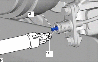
DISCONNECT FRONT SPEED SENSOR LH (for AWD)
-
DISCONNECT FRONT SPEED SENSOR RH (for AWD)
Tech Tips
Remove the RH side following the same procedure as for the LH side.
-
REMOVE FRONT AXLE SHAFT NUT LH (for AWD)
-
REMOVE FRONT AXLE SHAFT NUT RH (for AWD)
Tech Tips
Remove the RH side following the same procedure as for the LH side.
-
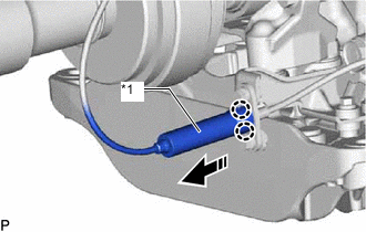
DISCONNECT FRONT HEIGHT CONTROL SENSOR SUB-ASSEMBLY LH
-
for 2WD:
-
for AWD:
-
-
DISCONNECT FRONT HEIGHT CONTROL SENSOR SUB-ASSEMBLY RH
Tech Tips
Remove the RH side following the same procedure as for the LH side.
-
DISCONNECT DISC BRAKE CYLINDER ASSEMBLY LH
-
DISCONNECT DISC BRAKE CYLINDER ASSEMBLY RH
Tech Tips
Remove the RH side following the same procedure as for the LH side.
-
REMOVE FRONT DISC LH
-
for 6-Pot Caliper:
-
except 6-Pot Caliper:
-
-
REMOVE FRONT DISC RH
Tech Tips
Remove the RH side following the same procedure as for the LH side.
-
REMOVE FRONT DISC BRAKE DUST COVER LH
-
REMOVE FRONT DISC BRAKE DUST COVER RH
Tech Tips
Remove the RH side following the same procedure as for the LH side.
-
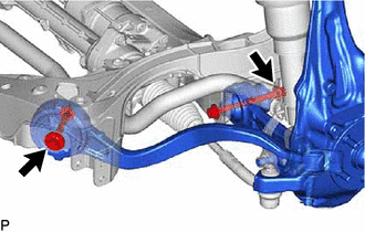
DISCONNECT TIE ROD ASSEMBLY LH
-
for 2WD:
-
for AWD:
-
-
DISCONNECT TIE ROD ASSEMBLY RH
Tech Tips
Remove the RH side following the same procedure as for the LH side.
-
DISCONNECT FRONT STABILIZER LINK ASSEMBLY LH (for 2WD)
-
DISCONNECT FRONT STABILIZER LINK ASSEMBLY RH (for 2WD)
Tech Tips
Remove the RH side following the same procedure as for the LH side.
-
DISCONNECT FRONT PNEUMATIC CYLINDER WITH SHOCK ABSORBER ASSEMBLY LH (for 2WD)
-
DISCONNECT FRONT PNEUMATIC CYLINDER WITH SHOCK ABSORBER ASSEMBLY RH (for 2WD)
Tech Tips
Remove the RH side following the same procedure as for the LH side.
-
DISCONNECT FRONT PNEUMATIC CYLINDER WITH SHOCK ABSORBER ASSEMBLY LH (for AWD)
-
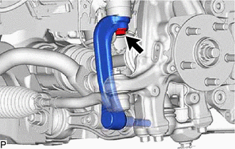
Remove the bolt. Then disconnect the absorber and absorber bracket.
-
-
DISCONNECT FRONT PNEUMATIC CYLINDER WITH SHOCK ABSORBER ASSEMBLY RH (for AWD)
Tech Tips
Remove the RH side following the same procedure as for the LH side.
-
DISCONNECT FRONT SHOCK ABSORBER ASSEMBLY LH (for 2WD)
-
DISCONNECT FRONT SHOCK ABSORBER ASSEMBLY RH (for 2WD)
Tech Tips
Remove the RH side following the same procedure as for the LH side.
-
DISCONNECT FRONT SHOCK ABSORBER ASSEMBLY LH (for AWD)
-
Remove the bolt. Then disconnect the absorber and absorber bracket.
-
-
DISCONNECT FRONT SHOCK ABSORBER ASSEMBLY RH (for AWD)
Tech Tips
Remove the RH side following the same procedure as for the LH side.
-
DISCONNECT STEERING KNUCKLE ASSEMBLY LH
Tech Tips
Remove the RH side following the same procedure as for the LH side.
-
for 2WD:
-
for AWD:
-
-
DISCONNECT STEERING KNUCKLE ASSEMBLY RH
Tech Tips
Remove the RH side following the same procedure as for the LH side.
-
REMOVE STEERING KNUCKLE LH (for 2WD)
-
Remove the 2 bolts, 2 nuts and steering knuckle LH.
-
-
REMOVE STEERING KNUCKLE RH (for 2WD)
Tech Tips
Remove the RH side following the same procedure as for the LH side.
-
REMOVE STEERING KNUCKLE LH (for AWD)
-
REMOVE STEERING KNUCKLE RH (for AWD)
Tech Tips
Remove the RH side following the same procedure as for the LH side.
-
REMOVE ENGINE SIDE COVER LH (for 2WD)
-
REMOVE ENGINE SIDE COVER RH (for 2WD)
Tech Tips
Remove the RH side following the same procedure as for the LH side.
-
REMOVE REAR LOWER ARM MOUNTING REINFORCEMENT SUB-ASSEMBLY LH (for 2WD)
-
REMOVE REAR LOWER ARM MOUNTING REINFORCEMENT SUB-ASSEMBLY RH (for 2WD)
Tech Tips
Remove the RH side following the same procedure as for the LH side.
-
REMOVE NO. 3 TURBO INSULATOR
-
REMOVE NO. 6 TURBO INSULATOR
-
Remove the bolt, nut and No. 6 turbo insulator.
-
-
INSTALL ENGINE HANGER
-
*a No. 1 Engine Hanger *b No. 2 Engine Hanger Install the No. 1 engine hanger and No. 2 engine hanger with the 4 bolts as shown in the illustration.
- Torque:
- 43 N*m { 438 kgf*cm, 32 ft.*lbf }
Tech Tips
No. 1 Engine Hanger 12281-70080 No. 2 Engine Hanger 12282-70050 Bolt 91552-F1040
-
-
DISCONNECT THROTTLE LINK CONNECTING ROD ASSEMBLY
-
*1 Cover Disconnect in this Direction Detach the 2 claws and disconnect the cover from the throttle link connecting rod assembly as shown in the illustration.
-
*1 Parking Lock Release Lever Assembly Cable End *2 Throttle Link Connecting Rod Assembly Cable End Disconnect the parking lock release lever assembly cable end from the throttle link connecting rod assembly cable end.
-
-
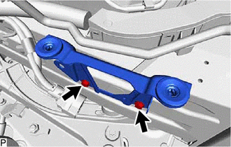
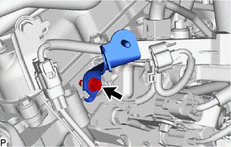
DISCONNECT NO. 2 GROUND WIRE
-
for 2WD:
-
Remove the bolt and disconnect the No. 2 ground wire.
-
-
for AWD:
-
Remove the bolt and disconnect the No. 2 ground wire.
-
-
-
REMOVE ENGINE AND TRANSMISSION ASSEMBLY (for 2WD)
-

Place Wooden Block or Plate Attachments Set the engine on an engine lifter.
Note
-
Place wooden blocks or plate lift attachments so that the engine is level.
-
With the exception of installing the engine assembly to an engine stand or removing the engine assembly from an engine stand, do not perform any work on the engine while it is suspended, as doing so is dangerous.
-
Never install attachments to the oil pan of the engine assembly or transmission as doing so may deform the oil pan.
-
-
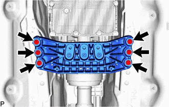
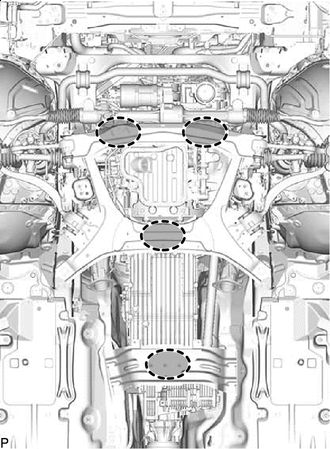
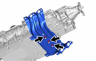
Remove the 6 bolts, and then separate the rear engine mounting member.
-
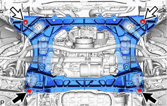
Bolt Nut Remove the 2 bolts and 2 nuts shown in the illustration.
-
Operate the engine lifter, then slowly remove the engine and transmission assembly from the vehicle.
Note
-
Make sure the engine is clear of all wiring and hoses.
-
While lowering the engine from the vehicle, do not allow it to contact the vehicle.
-
-
Attach an engine sling device and hang the engine with a chain block.
Note
Pay attention to the angle of the sling device as the engine assembly or engine hangers may be damaged or deformed if the angle is incorrect.
-
-
REMOVE ENGINE AND TRANSMISSION ASSEMBLY (for AWD)
-
Place Wooden Block or Plate Attachments Set the engine on an engine lifter.
Note
-
Place wooden blocks or plate lift attachments so that the engine is level.
-
With the exception of installing the engine assembly to an engine stand or removing the engine assembly from an engine stand, do not perform any work on the engine while it is suspended, as doing so is dangerous.
-
Never install attachments to the oil pan of the engine assembly or transmission as doing so may deform the oil pan.
-
-
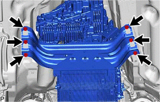
Remove the 6 bolts, and then separate the rear engine mounting member.
-
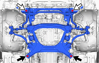
Bolt Nut Remove the 2 bolts and 2 nuts shown in the illustration.
-
Operate the engine lifter, then slowly remove the engine and transmission assembly from the vehicle.
Note
-
Make sure the engine is clear of all wiring and hoses.
-
While lowering the engine from the vehicle, do not allow it to contact the vehicle.
-
-
Attach an engine sling device and hang the engine with a chain block.
Note
Pay attention to the angle of the sling device as the engine assembly or engine hangers may be damaged or deformed if the angle is incorrect.
-
-
REMOVE ENGINE OIL LEVEL DIPSTICK GUIDE
-
REMOVE AIR FUEL RATIO SENSOR
-
REMOVE NO. 4 TURBO INSULATOR
-
REMOVE NO. 2 TURBO INSULATOR
-
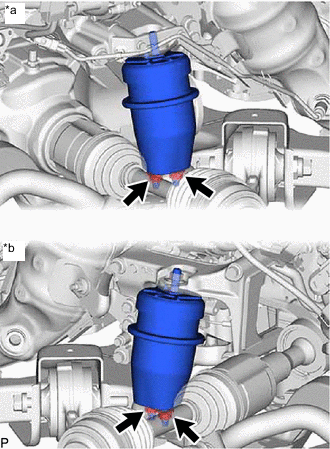
REMOVE DIFFERENTIAL PRESSURE SENSOR (w/ GPF)
-
for Bank 1:
-
for Bank 2:
-
-
REMOVE NO. 2 VACUUM PIPE (w/ GPF)
-
REMOVE NO. 1 VACUUM PIPE (w/ GPF)
-
REMOVE CONVERTER ASSEMBLY LH
-
REMOVE NO. 2 MANIFOLD STAY
-
REMOVE CONVERTER ASSEMBLY RH
-
REMOVE MANIFOLD STAY
-
REMOVE PROPELLER SHAFT HEAT INSULATOR
-
LOOSEN FRONT PROPELLER SHAFT ASSEMBLY (for AWD)
-
REMOVE FRONT PROPELLER SHAFT ASSEMBLY (for AWD)
-
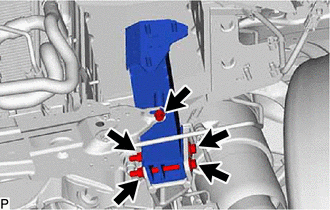
DISCONNECT FRONT FRAME ASSEMBLY (for AWD)
-
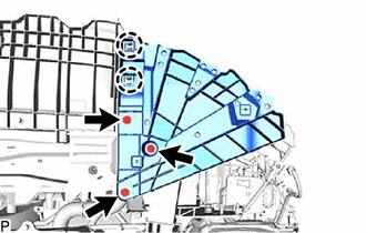
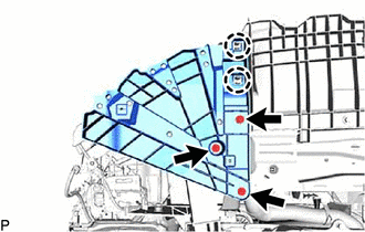
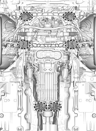
*a LH Side *b RH Side Remove the 4 nuts, then disconnect the front frame assembly from the engine.
-
-
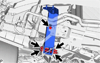
REMOVE FRONT ENGINE MOUNTING INSULATOR (for AWD)
Tech Tips
Only perform this procedure when replacement of the front engine mounting insulator is necessary.
-
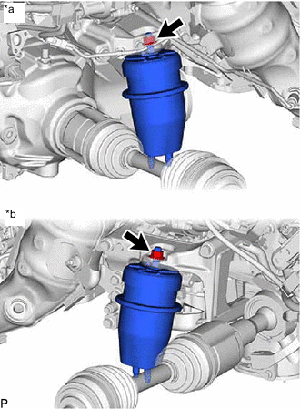
*a LH Side *b RH Side Remove the 2 nuts and 2 front engine mounting insulators.
-
-
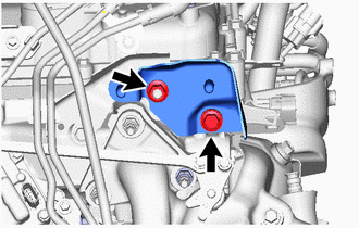
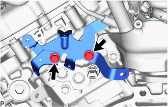
REMOVE FRONT NO. 1 ENGINE MOUNTING BRACKET RH (for AWD)
-
Remove the bolt and wire harness clamp bracket from the front No. 1 engine mounting bracket RH.
-
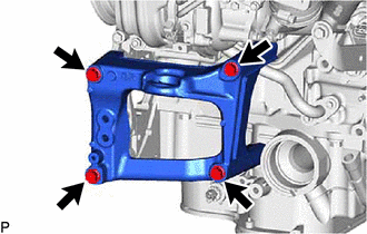
Remove the 4 bolts and front No. 1 engine mounting bracket RH.
-
-
REMOVE FLYWHEEL HOUSING SIDE STAY
-
w/ Stop And Start System:
-
w/o Stop And Start System:
-
-
REMOVE STARTER COVER
-
w/ Stop And Start System:
-
w/o Stop And Start System:
-
-
REMOVE STARTER ASSEMBLY
-
w/ Stop And Start System:
-
w/o Stop And Start System:
-
-
REMOVE FLYWHEEL HOUSING SIDE COVER
-
for 2WD:
-
for AWD:
-
-
REMOVE DRIVE PLATE AND TORQUE CONVERTER CLUTCH SETTING BOLT
-
for 2WD:
-
for AWD:
-
-
REMOVE AUTOMATIC TRANSMISSION ASSEMBLY (for 2WD)
-
REMOVE AUTOMATIC TRANSMISSION ASSEMBLY WITH TRANSFER (for AWD)
-
REMOVE DRIVE PLATE AND RING GEAR SUB-ASSEMBLY
-
REMOVE FRONT DRIVE SHAFT ASSEMBLY LH (for AWD)
-
REMOVE FRONT DRIVE SHAFT ASSEMBLY RH (for AWD)
-
REMOVE FRONT DRIVE SHAFT HOLE SNAP RING LH (for AWD)
-
REMOVE FRONT DIFFERENTIAL CARRIER ASSEMBLY (for AWD)
-
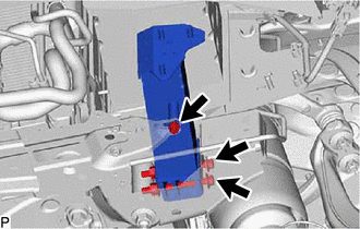
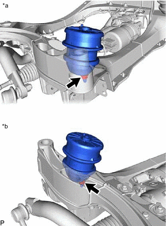
DISCONNECT FRONT FRAME CROSSMEMBER SUB-ASSEMBLY (for 2WD)
-
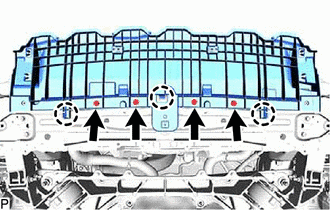
*a LH Side *b RH Side Remove the 2 bolts, then disconnect the front frame crossmember sub-assembly from the engine.
-
-
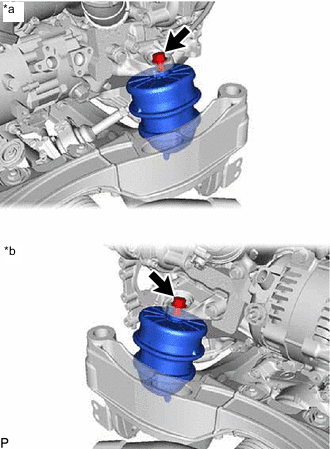
REMOVE FRONT ENGINE MOUNTING INSULATOR (for 2WD)
Tech Tips
Only perform this procedure when replacement of the front engine mounting insulator is necessary.
-
*a LH Side *b RH Side Remove the 2 nuts and 2 front engine mounting insulators.
-
-
REMOVE REAR ENGINE MOUNTING MEMBER
-
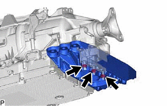
for 2WD:
-
Remove the 3 nuts and rear engine mounting member from the rear engine mounting insulator.
-
-
for AWD:
-
Remove the 3 nuts and rear engine mounting member from the rear engine mounting insulator.
-
-
-
REMOVE REAR ENGINE MOUNTING INSULATOR
-
for 2WD:
-
for AWD:
-
-
INSTALL ENGINE STAND
-
Install the engine to an engine stand with bolts.
Note
-
Pay attention to the angle of the sling device as the engine assembly or engine hangers may be damaged or deformed if the angle is incorrect.
-
With the exception of installing the engine assembly to an engine stand or removing the engine assembly from an engine stand, do not perform any work on the engine while it is suspended, as doing so is dangerous.
-
-
Remove the 4 bolts and 2 engine hangers.
-
-
REMOVE ENGINE WIRE
-
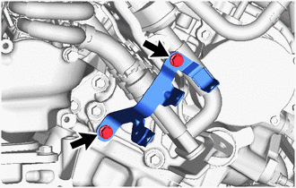
REMOVE EMISSION CONTROL VALVE BRACKET (w/ GPF)
-
Remove the bolt and emission control valve bracket.
-
-
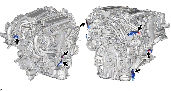
REMOVE WIRE HARNESS CLAMP BRACKET
-
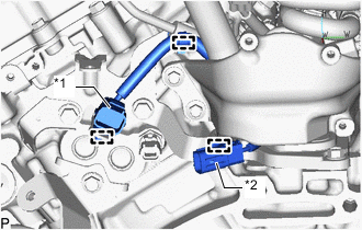
*1 No. 6 Engine Wire *2 Sensor Wire Detach the 2 clamps and disconnect the No. 6 engine wire from the wire harness clamp bracket.
-
Detach the clamp and disconnect the sensor wire from the wire harness clamp bracket.
-
Remove the 2 bolts and wire harness clamp bracket.
-
for LHD:
-
Remove the 2 bolts and wire harness clamp bracket.
-
-
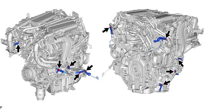
for 2WD:
-
Remove the 7 bolts and 7 wire harness clamp brackets.
-
-
for AWD:
-
Remove the 10 bolts and 9 wire harness clamp brackets.
-
-
-
REMOVE FRONT NO. 1 ENGINE MOUNTING BRACKET LH
-
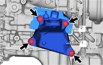
*1 Front No. 1 Engine Mounting Bracket LH *2 No. 8 Engine Cover for 2WD:
-
Remove the 4 bolts, front No. 1 engine mounting bracket LH and No. 8 engine cover.
-
-
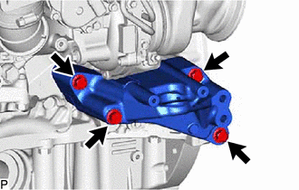
for AWD:
-
Remove the 4 bolts and front No. 1 engine mounting bracket LH.
-
-
-
REMOVE FRONT NO. 1 ENGINE MOUNTING BRACKET RH (for 2WD)
-
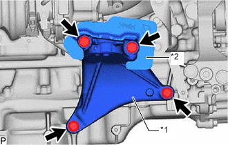
*1 Front No. 1 Engine Mounting Bracket RH *2 No. 7 Engine Cover Remove the 4 bolts, front No. 1 engine mounting bracket RH and No. 7 engine cover.
-
-
REMOVE FAN AND GENERATOR V BELT
-
REMOVE GENERATOR ASSEMBLY
-
REMOVE COMPRESSOR ASSEMBLY WITH PULLEY
-
for 2WD:
-
for AWD:
-