FUEL PUMP(for High Pressure) REMOVAL
CAUTION / NOTICE / HINT
The necessary procedures (adjustment, calibration, initialization or registration) that must be performed after parts are removed and installed, or replaced during fuel pump assembly removal/installation are shown below.
| Replaced Part or Performed Procedure | Necessary Procedure | Effect/Inoperative Function when Necessary Procedure not Performed | Link |
|---|---|---|---|
| Battery terminal is disconnected/reconnected | Memorize steering angle neutral point | LKA/LDA system | |
| Parking support brake system* | |||
| Pre-collision system | |||
| Adaptive high beam system | |||
Lighting system (EXT) |
|||
| Variable gear ratio steering system | |||
| Parking assist monitor system | |||
| Panoramic view monitor system | |||
| Initialize rear door sunshade system | Rear door sunshade system | ||
| Initialize power trunk lid system | Power trunk lid system | ||
| Replacement of fuel pump assembly | Inspection After Repair |
|
|
Click here Click here
CAUTION:
-
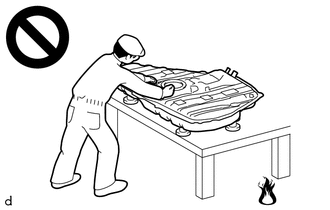
Never perform work on fuel system components near any possible ignition sources.
-
Vaporized fuel could ignite, resulting in a serious accident.
-
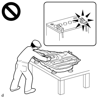
Do not perform work on fuel system components without first disconnecting the cable from the negative (-) battery terminal.
-
Sparks could cause vaporized fuel to ignite, resulting in a serious accident.
Note
This procedure includes the removal of small-head bolts. Refer to Small-Head Bolts of Basic Repair Hint to identify the small-head bolts.
PROCEDURE
-
DISCHARGE FUEL SYSTEM PRESSURE
-
PRECAUTION
Note
After turning the engine switch off, waiting time may be required before disconnecting the cable from the negative (-) battery terminal. Therefore, make sure to read the disconnecting the cable from the negative (-) battery terminal notices before proceeding with work.
-
DISCONNECT CABLE FROM NEGATIVE BATTERY TERMINAL
Note
When disconnecting the cable, some systems need to be initialized after the cable is reconnected.
-
REMOVE NO. 1 FUEL DELIVERY PIPE SUB-ASSEMBLY RH AND NO. 1 FUEL DELIVERY PIPE SUB-ASSEMBLY LH
-
REMOVE NO. 1 VACUUM SWITCHING VALVE ASSEMBLY
-
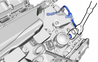
REMOVE NO. 1 FUEL PIPE SUB-ASSEMBLY
-
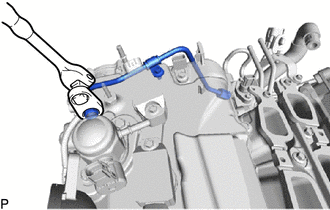
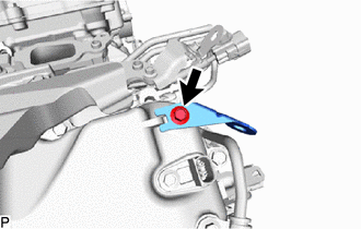
Using a 17 mm union nut wrench, loosen the union nut and disconnect the No. 1 fuel pipe sub-assembly from the fuel pump assembly.
-
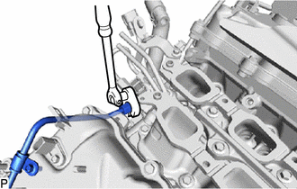
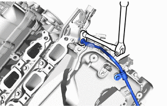
Using a 17 mm union nut wrench, loosen the union nut and disconnect the No. 1 fuel pipe sub-assembly from the No. 2 fuel delivery pipe sub-assembly RH.
-
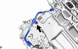
Remove the bolt and No. 1 fuel pipe sub-assembly from the cylinder head cover sub-assembly RH.
-
-
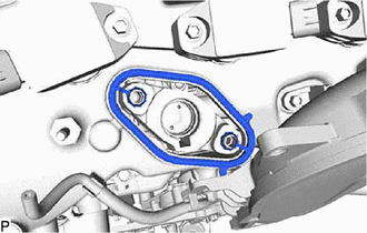
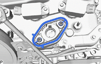
REMOVE FUEL PUMP ASSEMBLY (for Bank 1)
-
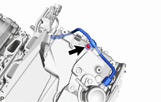
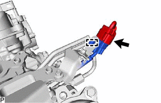
Disconnect the connector from the fuel pump assembly.
-
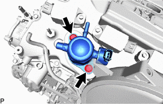
Remove the 2 bolts and fuel pump assembly from the cylinder head cover sub-assembly RH.
-

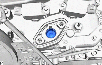
Remove the fuel pump spacer from the fuel pump assembly.
-
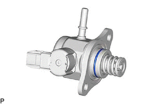
Remove the O-ring from the fuel pump assembly.
-
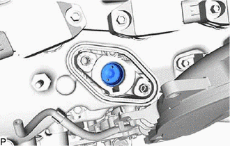
Remove the fuel pump lifter assembly from the fuel pump lifter guide assembly.
-
Remove the gasket from the cylinder head cover sub-assembly RH.
-
-
REMOVE NO. 2 FUEL PIPE SUB-ASSEMBLY
-
Using a 17 mm union nut wrench, loosen the union nut and disconnect the No. 2 fuel pipe sub-assembly from the fuel pump assembly.
-
Using a 17 mm union nut wrench, loosen the union nut and disconnect the No. 2 fuel pipe sub-assembly from the No. 2 fuel delivery pipe sub-assembly LH.
-
Remove the bolt and No. 2 fuel pipe sub-assembly from the cylinder head cover sub-assembly LH.
-
-
REMOVE FUEL PUMP ASSEMBLY (for Bank 2)
-
Disconnect the connector from the No. 5 engine wire.
-
Detach the clamp and No. 5 engine wire from the wire harness clamp bracket.
-
Remove the bolt and wire harness clamp bracket from the cylinder head cover sub-assembly LH.
-
Disconnect the connector from the fuel pump assembly.
-
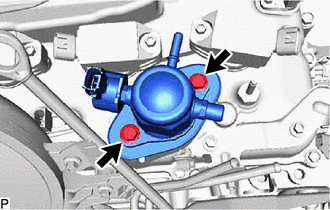
Remove the 2 bolts and fuel pump assembly from the cylinder head cover sub-assembly LH.
-
Remove the fuel pump spacer from the fuel pump assembly.
-
Remove the O-ring from the fuel pump assembly.
-
Remove the fuel pump lifter assembly from the fuel pump lifter guide assembly.
-
Remove the gasket from the cylinder head cover sub-assembly LH.
-