REAR SUSPENSION MEMBER REMOVAL

CAUTION / NOTICE / HINT
The necessary procedures (adjustment, calibration, initialization, or registration) that must be performed after parts are removed, installed, or replaced during the rear suspension member removal/installation are shown below.
| Necessary Procedure After Parts Removed/Installed/Replaced | |||||||||||||||||||||||||||||||||||||||||||||||||||
|---|---|---|---|---|---|---|---|---|---|---|---|---|---|---|---|---|---|---|---|---|---|---|---|---|---|---|---|---|---|---|---|---|---|---|---|---|---|---|---|---|---|---|---|---|---|---|---|---|---|---|---|
Click here Click here |
Tech Tips
-
Use the same procedure for the RH and LH sides.
-
The procedure listed below is for the LH side.
PROCEDURE
-
AIR SUSPENSION CONTROL PROHIBITED (w/ Air Suspension)
-
RELEASE PARKING BRAKE
-
FORCED RELEASE PARKING BRAKE
-
PRECAUTION
Note
After turning the engine switch off, waiting time may be required before disconnecting the cable from the battery negative (-) terminal. Therefore, make sure to read the disconnecting the cable from the battery negative (-) terminal notices before proceeding with work.
-
REMOVE LUGGAGE COMPARTMENT MAT SUB-ASSEMBLY
-
DISCONNECT CABLE FROM NEGATIVE BATTERY TERMINAL
Note
When disconnecting the cable, some systems need to be initialized after the cable is reconnected.
-
REMOVE REAR WHEEL
-
PARKING LOCK FORCED RELEASE
-
REMOVE ROCKER PANEL MOULDING PROTECTOR LH
-
REMOVE REAR WHEEL HOUSE LINER LH
-
REMOVE LUGGAGE COMPARTMENT FLOOR MAT
-
REMOVE LUGGAGE COMPARTMENT TRIM COVER LH
-
REMOVE LUGGAGE COMPARTMENT TRIM COVER RH
-
REMOVE LUGGAGE COMPARTMENT TRIM BOX (w/ Luggage Compartment Trim Box)
-
REMOVE TOOL BOX
-
REMOVE INNER LOWER LUGGAGE COMPARTMENT TRIM COVER
-
REMOVE FRONT LUGGAGE COMPARTMENT TRIM COVER (w/ Rear Air Conditioning System)
-
REMOVE FRONT LUGGAGE COMPARTMENT TRIM COVER (w/o Rear Air Conditioning System)
Tech Tips
Use the same procedure described for the front luggage compartment trim cover (w/ Rear Air Conditioning System).
-
REMOVE NO. 1 LUGGAGE COMPARTMENT LIGHT ASSEMBLY
-
REMOVE REAR LUGGAGE COMPARTMENT TRIM COVER
-
REMOVE ROPE HOOK ASSEMBLY
-
REMOVE REAR FLOOR FINISH PLATE
-
REMOVE LUGGAGE COMPARTMENT TRIM COVER ASSEMBLY LH
-
REMOVE NO. 1 FLOOR UNDER COVER (w/ Active Stabilizer System)
-
DISCONNECT REAR ACTIVE STABILIZER CONTROL ACTUATOR ASSEMBLY (w/ Active Stabilizer System)
-
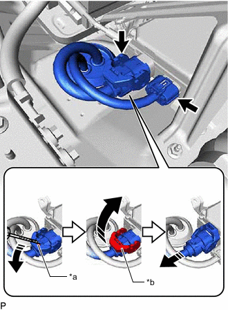
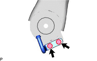
*a Lock of the Lock Lever *b Lock Lever Disconnect the 2 connectors from the active stabilizer control ECU assembly.
Tech Tips
When disconnecting a connector with lock lever, pull out the lock of the lock lever and turn the lock lever as shown in the illustration.
-
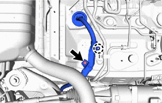
Remove the grommet of the rear active stabilizer control actuator assembly harness and pass the connector through the hole to the outside of the vehicle.
-
Remove the nut.
-
Disengage the claw and disconnect the rear active stabilizer control actuator assembly harness.
-
-
DISCONNECT PARKING BRAKE ACTUATOR ASSEMBLY WITH BRACKET
-
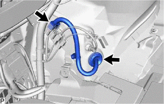
Disconnect the connector.
-
Remove the grommet of the electric parking brake actuator harness and pass the connector through the hole to the outside of the vehicle.
-
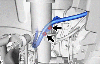
Remove the 2 nuts.
-
-
REMOVE REAR DIFFERENTIAL CARRIER ASSEMBLY
-
for V35A-FTS 2WD:
-
for 8GR-FKS and V35A-FTS AWD:
-
-
REMOVE REAR HEIGHT CONTROL SENSOR SUB-ASSEMBLY LH
-
REMOVE REAR HEIGHT CONTROL SENSOR SUB-ASSEMBLY RH
Tech Tips
Perform the same procedure as for the LH side.
-
REMOVE REAR SUSPENSION MEMBER SUB-ASSEMBLY
-
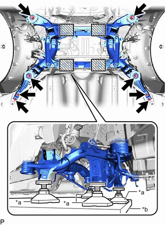
*a Attachment *b Engine Lifter 
Attachment placement location Support the rear suspension member sub-assembly with an engine lifter using 4 attachments or equivalent tools as shown in the illustration.
CAUTION:
-
The rear suspension member sub-assembly is a very heavy component. Make sure that it is supported securely.
-
If the rear suspension member sub-assembly is not securely supported, it may drop, resulting in serious injury.
Note
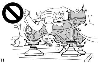
Use attachments to keep the rear suspension member sub-assembly level.
-
-
Remove the 8 bolts, rear lower suspension member stopper LH, rear lower suspension member stopper RH, rear lower suspension member stopper and rear suspension member sub-assembly.
-
Slowly lower the rear suspension member sub-assembly.
Note
When lowering the rear suspension member sub-assembly, be careful not to damage the vehicle body or other components installed to the vehicle.
-
-
REMOVE REAR STABILIZER LINK ASSEMBLY LH
-
REMOVE REAR STABILIZER LINK ASSEMBLY RH
Tech Tips
Perform the same procedure as for the LH side.
-
REMOVE PARKING BRAKE ACTUATOR ASSEMBLY WITH BRACKET
-
REMOVE REAR STABILIZER BAR (w/o Active Stabilizer System)
-
REMOVE REAR ACTIVE STABILIZER CONTROL ACTUATOR ASSEMBLY (w/ Active Stabilizer System)
-
REMOVE REAR NO. 1 DIFFERENTIAL MOUNT CUSHION
-
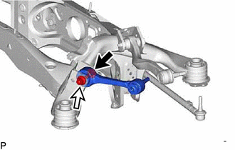
REMOVE LOWER CONTROL ARM ASSEMBLY LH
-
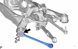

Bolt 
Nut Remove the bolt, nut and lower control arm assembly LH from the rear suspension member sub-assembly.
Note
Because the nut has its own stopper, do not turn the nut. Loosen the bolt with the nut secured.
-
-
REMOVE LOWER CONTROL ARM ASSEMBLY RH
Tech Tips
Perform the same procedure as for the LH side.
-
REMOVE REAR NO. 2 SUSPENSION ARM ASSEMBLY LH
-
Remove the nut, rear suspension arm attachment sub-assembly, rear No. 2 suspension toe adjust plate and rear No. 2 suspension arm assembly LH from the rear suspension member sub-assembly.
-
-
REMOVE REAR NO. 2 SUSPENSION ARM ASSEMBLY RH
Tech Tips
Perform the same procedure as for the LH side.
-
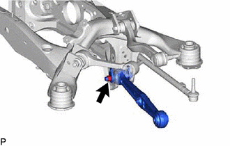
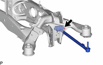
REMOVE REAR NO. 1 SUSPENSION ARM ASSEMBLY LH
-
Bolt Nut Remove the bolt, nut, washer and rear No. 1 suspension arm assembly LH from the rear suspension member sub-assembly.
-
-
REMOVE REAR NO. 1 SUSPENSION ARM ASSEMBLY RH
Tech Tips
Perform the same procedure as for the LH side.
-
REMOVE REAR UPPER CONTROL ARM ASSEMBLY LH
-
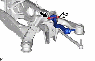
Bolt Nut Remove the bolt, nut, washer and rear upper control arm assembly LH from the rear suspension member sub-assembly.
Note
Because the nut has its own stopper, do not turn the nut. Loosen the bolt with the nut secured.
-
-
REMOVE REAR UPPER CONTROL ARM ASSEMBLY RH
Tech Tips
Perform the same procedure as for the LH side.
-
REMOVE TOE CONTROL LINK SUB-ASSEMBLY LH (w/o Dynamic Rear Steering)
-
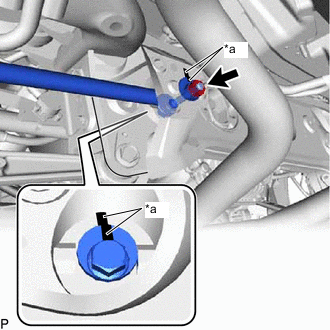
*a Matchmark Place matchmarks on the rear suspension toe adjust cam sub-assembly, rear No. 2 suspension toe adjust plate and rear suspension member sub-assembly.
-
Remove the nut, rear suspension toe adjust cam sub-assembly, rear No. 2 suspension toe adjust plate and toe control link sub-assembly LH from the rear suspension member sub-assembly.
-
-
REMOVE TOE CONTROL LINK SUB-ASSEMBLY RH (w/o Dynamic Rear Steering)
Tech Tips
Perform the same procedure as for the LH side.
-
REMOVE NO.4 EXHAUST PIPE SUPPORT BRACKET
-
Remove the 2 bolts and No.4 exhaust pipe support bracket from the rear suspension member sub-assembly.
-
-
REMOVE NO.5 EXHAUST PIPE SUPPORT BRACKET
Tech Tips
Perform the same procedure as for the No.4 exhaust pipe support bracket.
-
REMOVE REAR SUSPENSION MEMBER FRONT UPPER STOPPER
-
Remove the 2 rear suspension member front upper stoppers from the rear suspension member sub-assembly.
-
-
REMOVE REAR SUSPENSION MEMBER REAR UPPER STOPPER
-
Remove the 2 rear suspension member rear upper stoppers from the rear suspension member sub-assembly.
-
-
REMOVE REAR SUSPENSION MEMBER FRONT BODY MOUNTING CUSHION LH
-
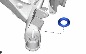
Using a chisel and hammer, bend the rear suspension member front body mounting cushion rib.
-
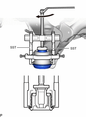
Using SST, remove the rear suspension member front body mounting cushion LH while applying grease into the clearance between the rear suspension member front body mounting cushion LH and the rear suspension member sub-assembly.
- SST
- 09950-40011 ( 09951-04020, 09952-04010, 09953-04030, 09954-04020, 09957-04010, 09958-04011 )
- 09950-60011 ( 09951-00540 )
Note
-
Apply grease to the threads and tip of the SST center bolt before use.
-
Be careful as the rear suspension member front body mounting cushion LH may fly out.
-
The rear suspension member front body mounting cushion LH cannot be reused.
-
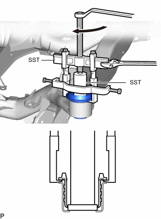
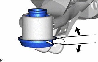
If the outer casing of the rear suspension member front body mounting cushion remains, insert SST between the rear suspension member front body mounting cushion and the rear suspension member sub-assembly, and then remove the outer casing. SST
- SST
- 09608-06041
- 09950-40011 ( 09951-04020, 09952-04010, 09953-04030, 09954-04020, 09957-04010, 09958-04011 )
- 09950-60011 ( 09951-00540 )
- 09950-60021 ( 09951-00680 )
-
-
REMOVE REAR SUSPENSION MEMBER FRONT BODY MOUNTING CUSHION RH
Tech Tips
Perform the same procedure as for the LH side.
-
REMOVE REAR SUSPENSION MEMBER REAR BODY MOUNTING CUSHION (for LH Side)
-
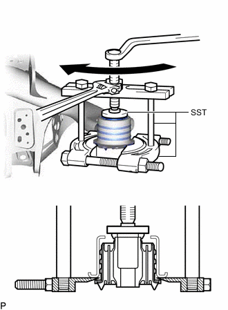
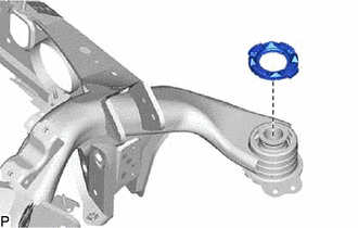
Using SST, remove the rear suspension member rear body mounting cushion while applying grease into the clearance between the rear suspension member rear body mounting cushion and the rear suspension member sub-assembly.
- SST
- 09608-06041
- 09950-00020
- 09950-00030
- 09950-40011 ( 09957-04010 )
- 09950-60011 ( 09951-00540 )
Note
-
Apply grease to the threads and tip of the SST center bolt before use.
-
Be careful as the rear suspension member rear body mounting cushion may fly out.
-
The rear suspension member rear body mounting cushion cannot be reused.
-
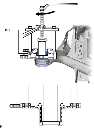
If the outer casing of the rear suspension member rear body mounting cushion remains, insert SST between the rear suspension member rear body mounting cushion and the rear suspension member sub-assembly, and then remove the outer casing. SST
- SST
- 09608-06041
- 09950-00020
- 09950-00030
- 09950-60021 ( 09951-00680 )
-
-
REMOVE REAR SUSPENSION MEMBER REAR BODY MOUNTING CUSHION (for RH Side)
Tech Tips
Perform the same procedure as for the LH side.