FUEL TANK(for Rear Air Fuel Ratio Sensor) REMOVAL
CAUTION / NOTICE / HINT
The necessary procedures (adjustment, calibration, initialization or registration) that must be performed after parts are removed and installed, or replaced during fuel tank assembly removal/installation are shown below.
| Replaced Part or Performed Procedure | Necessary Procedure | Effect/Inoperative Function when Necessary Procedure not Performed | Link |
|---|---|---|---|
| Battery terminal is disconnected/reconnected | Memorize steering angle neutral point | LKA/LDA System | |
| Intelligent clearance sonar system*1 | |||
| Pre-crash safety system | |||
| Lighting system (EXT)
|
|||
| Adaptive high beam system | |||
| Drive the vehicle until stop and start control is permitted (approximately 15 to 60 minutes) | Stop and start system | ||
| Memorize steering angle neutral point | Parking Assist Monitor System (w/ Parallel Parking Assist Function) | ||
| Parking Assist Monitor System (w/o Parallel Parking Assist Function) | |||
| Panoramic view monitor system | |||
| Initialize back door lock | Power door lock control system | ||
| Reset back door close position | Power back door system | ||
| Rear wheel alignment adjustment |
|
|
|
| Suspension, tires, etc. (The vehicle height changes because of suspension or tire replacement) |
|
|
|
| Rear television camera assembly optical axis (Back camera position setting) | Parking assist monitor system (w/ Parallel Parking Assist Function) | ||
| Rear television camera assembly optical axis (Back camera position setting) | Parking assist monitor system (w/o Parallel Parking Assist Function) | ||
|
Panoramic view monitor system | ||
| Initialize headlight ECU sub-assembly LH |
|
||
| Rear height control sensor sub-assembly | Initialize headlight ECU sub-assembly LH |
|
|
| Gas leak from exhaust system is repaired | Inspection After Repair |
|
Click here Click here
*2: w/ TFT Meter Type
PROCEDURE
-
REMOVE FUEL SUCTION TUBE WITH PUMP AND GAUGE ASSEMBLY
-
DRAIN FUEL
-
REMOVE REAR SUSPENSION MEMBER SUB-ASSEMBLY (for 2WD)
-
REMOVE REAR SUSPENSION MEMBER SUB-ASSEMBLY (for AWD)
-
REMOVE FRONT CENTER FLOOR COVER
-
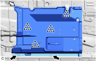

Screw 
Nut Remove the 2 screws and nut.
-
Disengage the 4 clips to remove the front center floor cover.
-
-
REMOVE CHARCOAL CANISTER PROTECTOR (w/ Canister Pump Module)
-
REMOVE CHARCOAL CANISTER PROTECTOR (w/o Canister Pump Module)
-
REMOVE NO. 1 FUEL TANK PROTECTOR SUB-ASSEMBLY
-
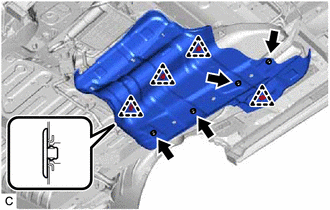
Remove the 4 clips, 4 nuts and No. 1 fuel tank protector sub-assembly.
-
-
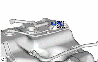
DISCONNECT FUEL TANK MAIN TUBE SUB-ASSEMBLY
-
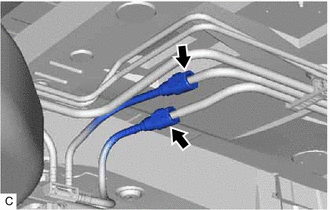
Disconnect the fuel tank main tube sub-assembly from the fuel pipe.
-
-
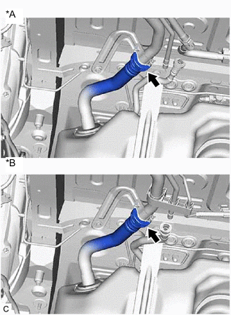
DISCONNECT FUEL TANK BREATHER TUBE
-
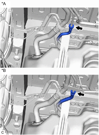
*A w/ Canister Pump Module *B w/o Canister Pump Module Disconnect the fuel tank breather tube from the fuel pipe.
-
-
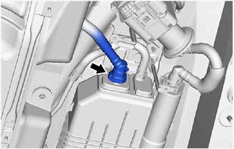
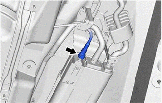
DISCONNECT FUEL TANK INLET TUBE SUB-ASSEMBLY
-
*A w/ Canister Pump Module *B w/o Canister Pump Module Disconnect the fuel tank inlet tube sub-assembly from the fuel tank filler pipe assembly.
-
-
DISCONNECT FUEL TANK EVAP/VENT TUBE SUB-ASSEMBLY (w/ Canister Pump Module)
-
Disconnect the fuel tank evap/vent tube sub-assembly from the charcoal canister assembly.
-
-
DISCONNECT FUEL CUT OFF VALVE WITH TUBE ASSEMBLY (w/o Canister Pump Module)
-
Disconnect the fuel cut off valve with tube assembly from the charcoal canister assembly.
-
-
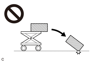
REMOVE FUEL TANK ASSEMBLY
CAUTION:
The fuel tank assembly is very heavy. Be sure to follow the procedure described in the repair manual, or the fuel tank assembly may fall off the engine lifter.
-
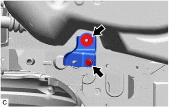
Remove the bolt, nut and rear fuel tank mounting bracket.
-
Remove the nut.
-
Support the fuel tank assembly using an engine lifter.
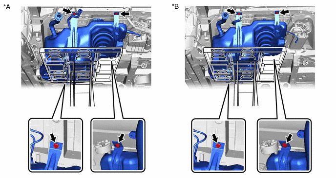
*A w/ Canister Pump Module *B w/o Canister Pump Module Tech Tips
Using height adjustment attachments and plate lift attachments, keep the fuel tank assembly horizontal.
-
Remove the 4 bolts, No. 1 fuel tank band sub-assembly LH and No. 1 fuel tank band sub-assembly RH.
-
Lower the engine lifter to remove the fuel tank assembly.
Note
-
Be careful not to drop the fuel tank assembly.
-
When removing the fuel tank assembly, tilt it slightly to prevent it from interfering with the surrounding parts.
-
-
-
REMOVE REAR FUEL TANK SIDE PLATE
-
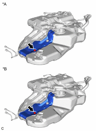
*A w/ Canister Pump Module *B w/o Canister Pump Module Remove the fuel tank cushion and rear fuel tank side plate from the fuel tank assembly.
-
-
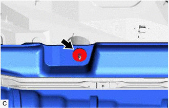
REMOVE FUEL TANK MAIN TUBE SUB-ASSEMBLY
-
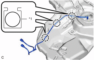
*1 Fuel Tank Main Tube Sub-assembly Disengage the 3 claws to remove the fuel tank main tube sub-assembly from the fuel tank assembly.
-
-
REMOVE FUEL TANK CUSHION SET
-
Remove the 2 fuel tank cushion sets and 2 No. 5 fuel tank cushions from the fuel tank assembly.
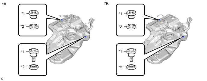
*A w/ Canister Pump Module *B w/o Canister Pump Module *1 Fuel Tank Cushion Set *2 No. 5 Fuel Tank Cushion
-
-
REMOVE TANK SUCTION TUBE SUPPORT
-
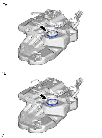
*A w/ Canister Pump Module *B w/o Canister Pump Module Remove the tank suction tube support from the fuel tank assembly.
-
-
REMOVE NO. 6 FUEL TANK CUSHION (w/ Canister Pump Module)
-
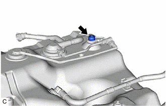
Remove the No. 6 fuel tank cushion from the fuel tank assembly.
-
-
REMOVE CHECK VALVE BRACKET (w/ Canister Pump Module)
-
Disengage the clamp to remove the check valve bracket from the fuel tank assembly.
-