UPPER INSTRUMENT PANEL REMOVAL
CAUTION / NOTICE / HINT
Tech Tips
-
Use the same procedure for RHD and LHD vehicles.
-
The procedure listed below is for LHD vehicles.
-
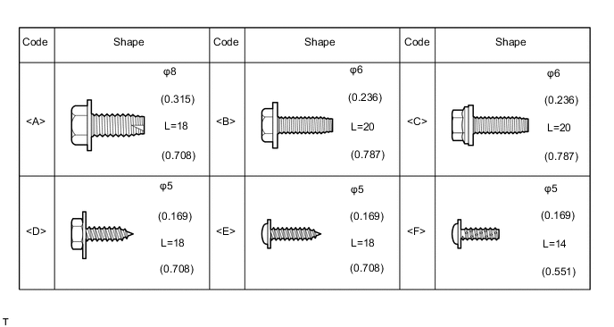
All bolts, screws and nuts relevant to installing and removing the instrument panel are shown along with their alphabet code in the table below.
PROCEDURE
-
DISCONNECT CABLE FROM NEGATIVE BATTERY TERMINAL
CAUTION:
Wait at least 90 seconds after disconnecting the cable from the negative (-) battery terminal to disable the SRS system.
Note
When disconnecting the cable, some systems need to be initialized after the cable is reconnected Click here.
-
REMOVE FRONT DOOR SCUFF PLATE LH
-
REMOVE FRONT DOOR SCUFF PLATE RH
Tech Tips
Use the same procedure for the LH side and RH side.
-
REMOVE COWL SIDE TRIM BOARD LH
-
REMOVE COWL SIDE TRIM BOARD RH
Tech Tips
Use the same procedure for the LH side and RH side.
-
REMOVE FRONT DOOR OPENING TRIM WEATHERSTRIP LH
-
REMOVE FRONT DOOR OPENING TRIM WEATHERSTRIP RH
Tech Tips
Use the same procedure for the LH side and RH side.
-
REMOVE FRONT PILLAR GARNISH CORNER PIECE LH
-
REMOVE FRONT PILLAR GARNISH CORNER PIECE RH
Tech Tips
Use the same procedure for the LH side and RH side.
-
REMOVE FRONT PILLAR GARNISH LH (w/ Curtain Shield Airbag)
-
REMOVE FRONT PILLAR GARNISH RH (w/ Curtain Shield Airbag)
Tech Tips
Use the same procedure for the LH side and RH side.
-
REMOVE FRONT PILLAR GARNISH LH (w/o Curtain Shield Airbag)
-
REMOVE FRONT PILLAR GARNISH RH (w/o Curtain Shield Airbag)
Tech Tips
Use the same procedure for the LH side and RH side.
-
REMOVE NO. 1 METER HOOD CLUSTER
-

Disengage the 2 clips and remove the No. 1 meter hood cluster.
-
-
REMOVE NO. 2 METER HOOD CLUSTER
-
Disengage the 3 clips and remove the No. 2 meter hood cluster.
-
-
REMOVE INSTRUMENT CLUSTER FINISH PANEL ASSEMBLY
-
REMOVE COMBINATION METER ASSEMBLY
-
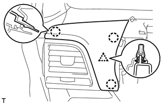
REMOVE UPPER INSTRUMENT CENTER CLUSTER FINISH PANEL
-
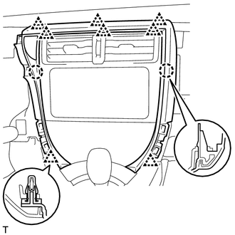
Disengage the 8 clips and 2 claws, remove the upper instrument center cluster finish panel.
-
Disconnect the connector.
-
-
REMOVE HAZARD WARNING SIGNAL SWITCH ASSEMBLY
-
REMOVE CENTER INSTRUMENT CLUSTER FINISH PANEL SUB-ASSEMBLY (w/o Radio Receiver)
-
Disengage the 4 clips and remove the center instrument cluster finish panel sub-assembly.
-
-
REMOVE RADIO RECEIVER ASSEMBLY (w/ Radio Receiver)
-
REMOVE CENTER INSTRUMENT PANEL REGISTER ASSEMBLY
-

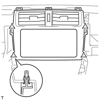
Disengage the 8 claws and remove the center instrument panel register assembly.
-
-
REMOVE UPPER INSTRUMENT PANEL FINISH PANEL SUB-ASSEMBLY
-
Disengage the clip and 3 claws, remove the upper instrument panel finish panel sub-assembly.
-
-
REMOVE NO. 2 INSTRUMENT PANEL BOX DOOR SUB-ASSEMBLY
-
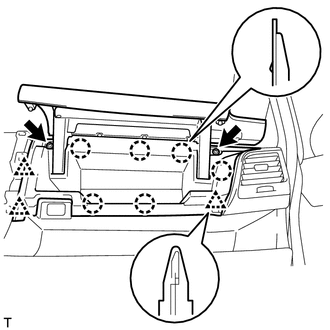
Remove the 2 screws.
-
Disengage the 3 clips and 6 claws, remove the No. 2 instrument panel box door sub-assembly.
-
-
REMOVE CONSOLE COMPARTMENT DOOR CUSHION
-
Disengage the claw and remove the 2 console compartment door cushions from the No. 2 instrument panel box door sub-assembly.
-
-
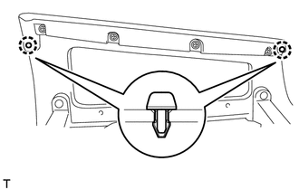
REMOVE NO. 1 INSTRUMENT PANEL REGISTER ASSEMBLY
-

Disengage the 4 clips, and remove the No. 1 instrument panel register assembly.
-
-
REMOVE NO. 2 INSTRUMENT PANEL REGISTER ASSEMBLY
Tech Tips
Use the same procedure for the No. 1 instrument panel register assembly.
-
SEPARATE INSTRUMENT PANEL PASSENGER AIRBAG ASSEMBLY
-
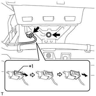
Text in illustration *1 Slider Disconnect the connector as shown in the illustration.
-
Remove the bolt and separate the instrument panel passenger airbag assembly.
-
-
REMOVE UPPER INSTRUMENT PANEL SUB-ASSEMBLY
-
Remove the 2 clips.
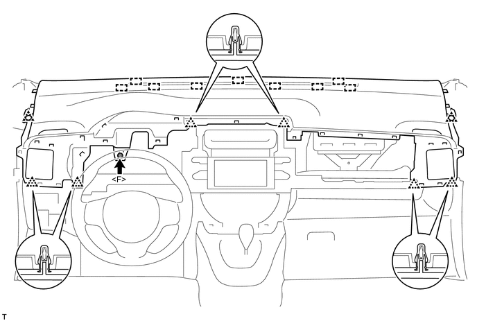
-
Remove the <F> screw.
-
Disengage the 6 clips and 9 guides, remove the upper instrument panel sub-assembly.
Note
Be careful not to damage the upper instrument panel sub-assembly when removing it.
-
-
REMOVE NO. 1 INSTRUMENT PANEL MOUNTING BRACKET
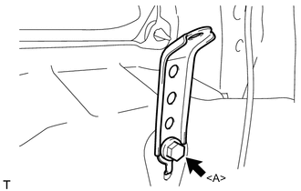
-
Remove the <A> bolt and the No. 1 instrument panel mounting bracket.
Tech Tips
Use the same procedure for the LH side and RH side.
-