VEHICLE STABILITY CONTROL SYSTEM TRC OFF Indicator Light Remains ON
DESCRIPTION
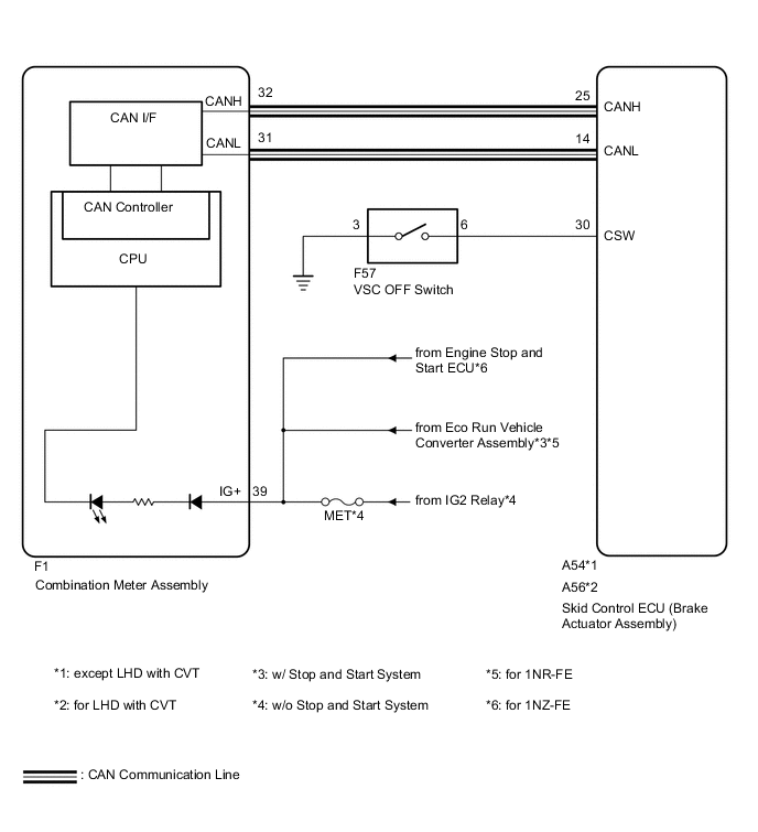
The skid control ECU (brake actuator assembly) is connected to the combination meter via CAN communication.
Pressing the VSC OFF switch turns off traction control and pressing and holding this switch turns off traction and VSC controls. If traction control turns off, the TRC OFF indicator light will come on.
If VSC and traction controls turn off, the TRC OFF indicator and VSC OFF indicator lights will come on.
The TRC OFF indicator light is illuminated when the TRC control is prohibited by operating the VSC OFF switch.
By Pressing the VSC OFF switch for a short time, the TRC OFF mode is activated, and the TRC control is prohibited, and the TRC OFF indicator light in the combination meter is illuminated.
By pressing the VSC OFF switch for 3 seconds or longer, the VSC OFF mode is activated, the VSC and TRC controls are prohibited, and both the VSC OFF indicator light and the TRC OFF indicator light are illuminated.
WIRING DIAGRAM
CAUTION / NOTICE / HINT
Note
-
When replacing the brake actuator assembly, perform zero point calibration Click here.
-
Inspect the fuses for circuits related to this system before performing the following inspection procedure.
PROCEDURE
-
CHECK CAN COMMUNICATION SYSTEM
-
Check if CAN communication system DTCs are output Click here.
Result Result Proceed to DTC is not output A DTC is output B
B 
CHECK CAN COMMUNICATION SYSTEM Click here
A 
-
-
CHECK IF BRAKE ACTUATOR ASSEMBLY CONNECTOR SECURELY CONNECTED
-
Check if the skid control ECU (brake actuator assembly) connector is securely connected.
OK The connector is securely connected.
NG
CONNECT CONNECTOR TO ECU CORRECTLY
OK
-
-
INSPECT BATTERY
-
Check the battery voltage.
Standard voltage 11 to 14 V Result Result Proceed to OK A NG (for 1ND-TV) B NG (for 1NR-FE) C NG (for 1NZ-FE) D
B
CHECK AND REPLACE CHARGING SYSTEM OR BATTERY Click here
C
CHECK AND REPLACE CHARGING SYSTEM OR BATTERY Click here
D
CHECK OR REPLACE CHARGING SYSTEM OR BATTERY Click here
A
-
-
CHECK HARNESS AND CONNECTOR (CSW)
-
Turn the ignition switch off.
-
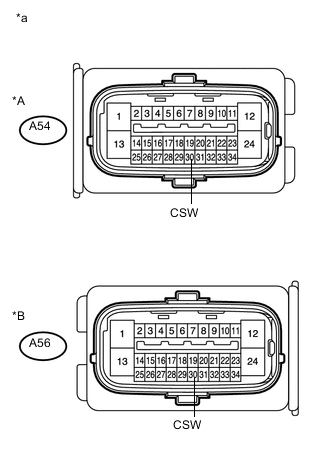
Text in Illustration *A except LHD with CVT *B for LHD with CVT *a Front view of wire harness connector
(to Skid control ECU (Brake actuator assembly))
Disconnect the A54*1 or A56*2 skid control ECU (brake actuator assembly) connector.
-
*1: except LHD with CVT
-
*2: for LHD with CVT
-
-
Measure the resistance according to the value(s) in the table below.
Standard Resistance (Check for Open) except LHD with CVT Tester Connection Switch Condition Specified Condition A54-30 (CSW) - Body ground VSC OFF Switch held ON Below 1 Ω for LHD with CVT Tester Connection Switch Condition Specified Condition A56-30 (CSW) - Body ground VSC OFF Switch held ON Below 1 Ω Standard Resistance (Check for Short) except LHD with CVT Tester Connection Switch Condition Specified Condition A54-30 (CSW) - Body ground VSC OFF Switch OFF (Not pressed) 10 kΩ or higher for LHD with CVT Tester Connection Switch Condition Specified Condition A56-30 (CSW) - Body ground VSC OFF Switch OFF (Not pressed) 10 kΩ or higher -
Reconnect the A54*1 or A56*2 skid control ECU (brake actuator assembly) connector.
-
*1: except LHD with CVT
-
*2: for LHD with CVT
-
NG 
INSPECT VSC OFF SWITCH Click here
OK
-
-
INSPECT COMBINATION METER ASSEMBLY
-
Connect the intelligent tester to the DLC3.
-
Perform Active Test of the combination meter assembly using the intelligent tester Click here.
OK The TRC OFF indicator light turns on or off in accordance with the intelligent tester. Result Result Proceed to NG A OK (for LHD) B OK (for RHD) C
B
REPLACE BRAKE ACTUATOR ASSEMBLY Click here
C
REPLACE BRAKE ACTUATOR ASSEMBLY Click here
A
-
-
REPLACE COMBINATION METER ASSEMBLY
-
Turn the ignition switch off.
-
Replace the combination meter assembly Click here.
NEXT
-
-
INSPECT COMBINATION METER ASSEMBLY
-
Perform Active Test of the combination meter assembly using the intelligent tester Click here.
OK The VSC OFF indicator light turns on or off in accordance with the intelligent tester. Result Result Proceed to NG A OK (for LHD) B OK (for RHD) C
A
END
B
REPLACE BRAKE ACTUATOR ASSEMBLY Click here
C
REPLACE BRAKE ACTUATOR ASSEMBLY Click here
-
-
INSPECT VSC OFF SWITCH
-
Remove the VSC OFF switch Click here.
-
Inspect the VSC OFF switch Click here.
-
Reconnect the VSC OFF switch connector.
NG
REPLACE VSC OFF SWITCH Click here
OK
-
-
CHECK HARNESS AND CONNECTOR (BRAKE ACTUATOR ASSEMBLY)
-
Disconnect the A54*1 or A56*2 skid control ECU (brake actuator assembly) connector and the VSC OFF switch connector.
-
*1: except LHD with CVT
-
*2: for LHD with CVT
-
-
Measure the resistance according to the value(s) in the table below.
Standard Resistance (Check for Open) except LHD with CVT Tester Connection Condition Specified Condition A54-30 (CSW) - F57-6 Always Below 1 Ω F57-3 - Body ground Always Below 1 Ω for LHD with CVT Tester Connection Condition Specified Condition A56-30 (CSW) - F57-6 Always Below 1 Ω F57-3 - Body ground Always Below 1 Ω Standard Resistance (Check for Short) except LHD with CVT Tester Connection Condition Specified Condition A54-30 (CSW) or F57-6 - Body ground Always 10 kΩ or higher for LHD with CVT Tester Connection Condition Specified Condition A56-30 (CSW) or F57-6 - Body ground Always 10 kΩ or higher -
Reconnect the A54*1 or A56*2 skid control ECU (brake actuator assembly) connector and the VSC OFF switch connector.
-
*1: except LHD with CVT
-
*2: for LHD with CVT
-
OK
CHECK INTERMITTENT PROBLEMS (SYMPTOM SIMULATION) Click here
NG
REPAIR OR REPLACE HARNESS OR CONNECTOR
-