POWER WINDOW CONTROL SYSTEM Rear Power Window RH Auto Up / Down Function does not Operate with Rear Power Window Switch RH
DESCRIPTION
If the manual up and down functions operate normally but the auto up and down functions do not, the fail-safe mode may be functioning.
If power window initialization Click here has not been performed, the auto up and down functions will not operate.
Tech Tips
If the pulse sensor built into the power window regulator motor assembly (for rear RH door) malfunctions, the power window control system enters fail-safe mode. The remote up and down and auto up and down functions cannot be operated during fail-safe mode. However, the power window can be closed by holding the rear power window regulator switch assembly (for RH door) at the auto up position, and opened manually by pushing down the rear power window regulator switch assembly (for RH door).
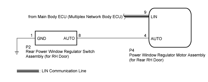
WIRING DIAGRAM
INSPECTION PROCEDURE
Note
-
The power window control system uses a LIN communication system. Inspect the communication function by following How to Proceed with Troubleshooting Click here. Troubleshoot the power window control system after confirming that the communication system is functioning properly.
-
If the power window regulator motor assembly (for rear RH door) has been replaced with a new one, initialize the power window control system Click here.
PROCEDURE
-
READ VALUE USING GTS (RR-Door Motor)
-
Connect the GTS to the DLC3.
-
Turn the power switch on (IG).
-
Turn the GTS on.
-
Enter the following menus: Body Electrical / RR-Door Motor / Data List.
-
Read the Data List according to the display on the GTS.
RR-Door Motor Tester Display Measurement Item/Range Normal Condition Diagnostic Note RR Door P/W Auto SW Rear RH door power window auto switch signal / OFF or ON OFF: Rear RH power window auto switch not operated
ON: Rear RH power window auto switch operated
- OK On the GTS screen, ON or OFF is displayed accordingly.
NG 
INSPECT REAR POWER WINDOW REGULATOR SWITCH ASSEMBLY (for RH Door) Click here
OK 
-
-
PERFORM INITIALIZATION (for Rear RH Door)
-
Initialize the power window regulator motor assembly (for rear RH door) Click here.
NEXT
-
-
CHECK POWER WINDOW CONTROL SYSTEM (AUTO UP/DOWN FUNCTION)
-
Check that the rear RH door power window moves when the auto up and down functions of the rear power window regulator switch assembly (for RH door) are operated Click here.
OK Rear RH door auto up and down functions are normal.
NG 
REPLACE POWER WINDOW REGULATOR MOTOR ASSEMBLY (for Rear RH Door) Click here
OK 
END (PROBLEM DUE TO INITIALIZATION FAILURE)
-
-
INSPECT REAR POWER WINDOW REGULATOR SWITCH ASSEMBLY (for RH Door)
-
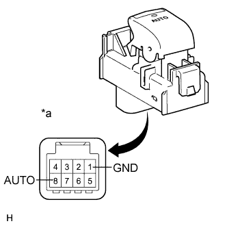
Text in Illustration *a Component without harness connected
(Rear Power Window Regulator Switch Assembly (for RH Door))
Remove the rear power window regulator switch assembly (for RH door) Click here.
-
Measure the resistance according to the value(s) in the table below.
Standard Resistance Tester Connection Condition Specified Condition 8 (AUTO) - 1 (GND) Auto up or auto down position Below 1 Ω
NG
REPLACE REAR POWER WINDOW REGULATOR SWITCH ASSEMBLY (for RH Door) Click here
OK
-
-
CHECK HARNESS AND CONNECTOR (REAR RH DOOR SWITCH - REAR RH DOOR MOTOR)
-
Disconnect the P4 power window regulator motor assembly (for rear RH door) connector.
-
Measure the resistance according to the value(s) in the table below.
Standard Resistance Tester Connection Condition Specified Condition P2-8 (AUTO) - P4-4 (AUTO) Always Below 1 Ω P2-8 (AUTO) - Body ground Always 10 kΩ or higher P4-4 (AUTO) - Body ground Always 10 kΩ or higher
NG
REPAIR OR REPLACE HARNESS OR CONNECTOR
OK
REPLACE POWER WINDOW REGULATOR MOTOR ASSEMBLY (for Rear RH Door) Click here
-