FRONT DOOR REASSEMBLY

-
INSTALL FRONT DOOR FRONT WINDOW FRAME MOULDING
-
Clean the vehicle body surface.
-
Remove any caulking sponge from the vehicle body.
-
Wipe off any tape adhesive residue with cleaner.
-
-
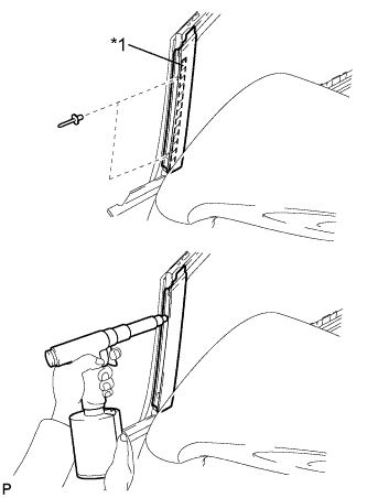
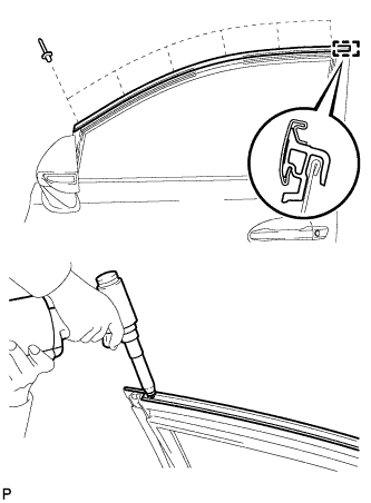
Text in Illustration *1 Caulking Sponge Install a new front door front window frame moulding.
-
Remove the release paper from the face of the front door front window frame moulding.
Tech Tips
After removing the release paper, keep the exposed adhesive free from foreign matter.
-
Engage the front door front window frame moulding to the door frame.
-
Using an air riveter or hand riveter with a nose piece, install the front door front window frame moulding with 2 new rivets.
Tech Tips
If the rivet cannot be cut, pull it once and cut it.
Note
-
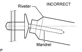
Do not pry the rivet with the riveter, as this will cause damage to the riveter and mandrel.
-
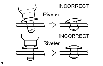
Confirm that the rivets are seated properly against the moulding. Do not tilt the riveter when installing the rivet to the moulding. Do not leave any space between the rivet head and moulding.
-
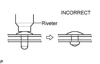
Do not leave any space between the moulding and door frame. Firmly hold the 2 items together while installing the rivet.
-
-
-
-
INSTALL FRONT DOOR UPPER WINDOW FRAME MOULDING
-
Engage the front door upper window frame moulding to the door frame.
-
Using an air riveter or hand riveter with a nose piece, install the front door upper window frame moulding with 6 new rivets.
Tech Tips
If the rivet cannot be cut, pull it once and cut it.
Note
-
Do not pry the rivet with the riveter, as this will cause damage to the riveter and mandrel.
-
Confirm that the rivets are seated properly against the moulding. Do not tilt the riveter when installing the rivet to the moulding. Do not leave any space between the rivet head and moulding.
-

Do not leave any space between the moulding and door frame. Firmly hold the 2 items together while installing the rivet.
-
-
-
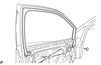
INSTALL FRONT DOOR PANEL SUB-ASSEMBLY
-
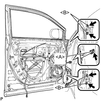
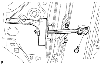
Install the front door panel sub-assembly with the 4 bolts <B>.
- Torque:
- 27 N*m { 275 kgf*cm, 20 ft.*lbf }
Note
To prevent damage, when installing the front door panel sub-assembly, make sure that there are enough people available to hold it securely.
-
Apply adhesive to the threads of the bolt <A>.
Adhesive Toyota Genuine Adhesive 1324, Three Bond 1324 or equivalent -
Engage the front door check assembly with the bolt <A>.
- Torque:
- 27 N*m { 275 kgf*cm, 20 ft.*lbf }
-
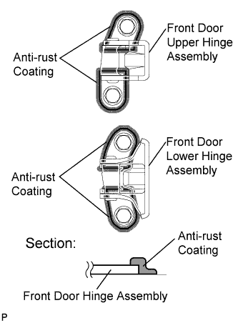
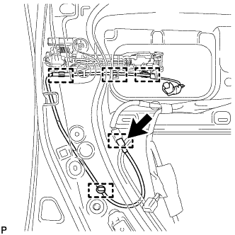
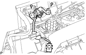
Using a brush, apply anti-rust coating to the front door hinge assembly as shown in the illustration.
-
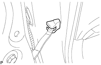
Connect each connector.
-
Engage each clamp.
-
-
INSTALL COWL SIDE TRIM SUB-ASSEMBLY
-
Engage the 2 clips to install the cowl side trim sub-assembly LH.
-
Install the clip.
-
-
INSTALL FRONT DOOR SCUFF PLATE
-
w/ Illumination:
-
Connect the connector.
-
-
Engage the 4 clips, guide and 7 claws, and install the front door scuff plate LH.
-
-
INSTALL FRONT DOOR REAR WINDOW FRAME MOULDING
Tech Tips
When installing the front door rear window frame moulding, heat the vehicle body and front door rear window frame moulding using a heat light.
Heating Temperature Item Temperature Vehicle Body 40 to 60°C (104 to 140°F) Moulding 20 to 30°C (68 to 86°F) Note
Do not heat the vehicle body or front door rear window frame moulding excessively.
-
Clean the vehicle body surface.
-
Using a heat light, heat the vehicle body surface.
-
Remove the double-sided tape from the vehicle body.
-
Wipe off any tape adhesive residue with cleaner.
-
-
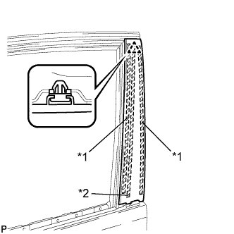
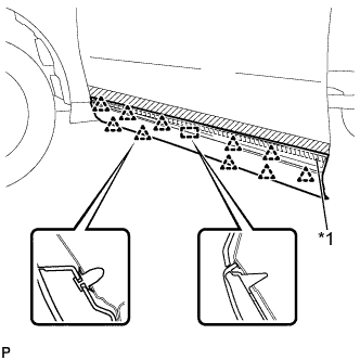
Text in Illustration *1 Double-sided Tape *2 Caulking Sponge Install a new front door rear window frame moulding.
-
Using a heat light, heat the vehicle body and front door rear window frame moulding.
-
Remove the release paper from the face of the front door rear window frame moulding.
Tech Tips
After removing the release paper, keep the exposed adhesive free from foreign matter.
-
Install the front door rear window frame moulding with the clip.
-
-
-
INSTALL FRONT DOOR BELT MOULDING ASSEMBLY
-
Engage the 6 claws to install the front door belt moulding assembly.
-
-
INSTALL FRONT DOOR OUTSIDE MOULDING SUB-ASSEMBLY
Tech Tips
When installing the front door outside moulding sub-assembly, heat the vehicle body and front door outside moulding sub-assembly using a heat light.
Heating Temperature Item Temperature Vehicle Body 40 to 60°C (104 to 140°F) Moulding 20 to 30°C (68 to 86°F)
-
Clean the vehicle body surface.
-
Using a heat light, heat the vehicle body surface.
-
Remove the double-sided tape from the vehicle body.
-
Wipe off any tape adhesive residue with cleaner.
-
-
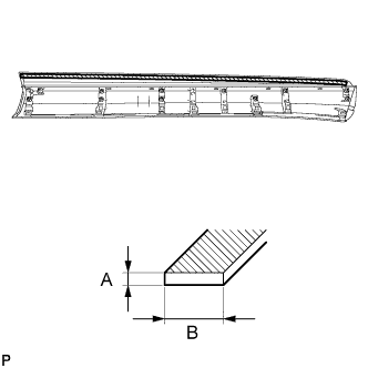
Clean the front door outside moulding sub-assembly.
Standard Measurement Dimension Measurement A 1.2 mm (0.0472 in.) B 10.0 mm (0.394 in.)
-
Using a heat light, heat the front door outside moulding sub-assembly.
-
Remove the double-sided tape from the front door outside moulding sub-assembly.
-
Wipe off any tape adhesive residue with cleaner.
-
Apply new double-sided tape to the front door outside moulding sub-assembly.
-
-
Install 10 new clips (quarter vent louver retainer) to the front door outside moulding sub-assembly.
-
Install the bolt to the front door outside moulding sub-assembly.
-
Install a new gasket to the bolt.
-
Text in Illustration *1 Double-sided Tape Install the front door outside moulding sub-assembly.
-
Using a heat light, heat the vehicle body and front door outside moulding sub-assembly.
-
Remove the release paper from the front door outside moulding sub-assembly.
Tech Tips
After removing the release paper, keep the exposed adhesive free from foreign matter.
-
Engage the 10 clips and guide to install the front door outside moulding sub-assembly.
-
-
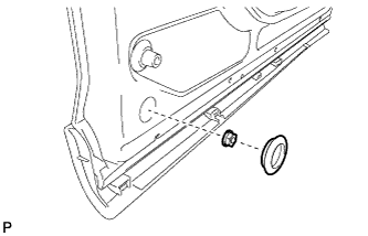
Install the nut and hole plug.
-
-
INSTALL FRONT DOOR LOWER OUTSIDE MOULDING
-
Install 5 new clips (quarter vent louver retainer) to the front door lower outside moulding.
-
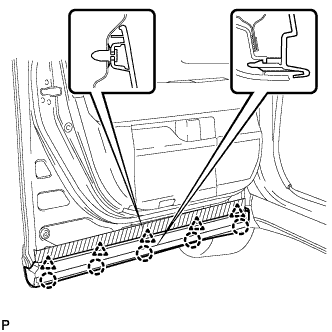
Engage the 5 clips and 5 claws to install the front door lower outside moulding.
-
-
INSTALL FRONT DOOR WEATHERSTRIP
-
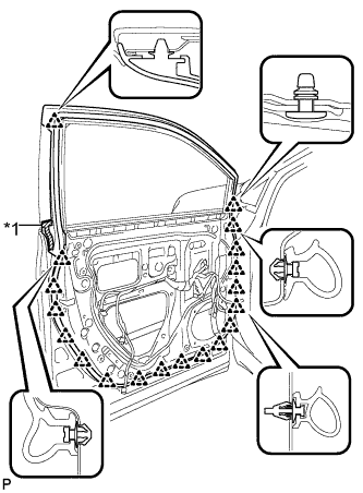
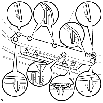
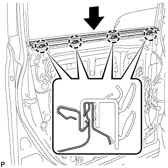
Text in Illustration *1 Double-sided Tape Engage the 19 clips and install a new front door weatherstrip.
-
-
INSTALL FRONT DOOR CHECK ASSEMBLY
-
Apply MP grease to the sliding areas of the front door check assembly.
-
Apply adhesive to the threads of the bolt.
Adhesive Toyota Genuine Adhesive 1324, Three Bond 1324 or equivalent -
Install the front door check assembly with the bolt and 2 nuts.
- Torque:
- Bolt
- 27 N*m { 275 kgf*cm, 20 ft.*lbf }
- Nut
- 8.0 N*m { 82 kgf*cm, 71 in.*lbf }
-
-
INSTALL FRONT DOOR CHECK COVER
-
Install the front door check cover.
-
-
INSTALL FRONT DOOR LOCK OPEN ROD
-
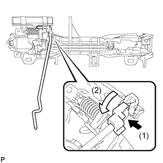
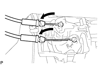
Install the front door lock open rod as indicated by the arrows in the order shown in the illustration.
-
-
INSTALL FRONT DOOR OUTSIDE HANDLE FRAME SUB-ASSEMBLY
-
Apply MP grease to the sliding parts on the front door outside handle frame sub-assembly.
-
Engage the door handle nut and claw.
-
Using a T30 "TORX" socket wrench, install the front door outside handle frame sub-assembly with the screw.
- Torque:
- 4.0 N*m { 41 kgf*cm, 35 in.*lbf }
-
-
INSTALL ELECTRICAL KEY WIRE HARNESS
-
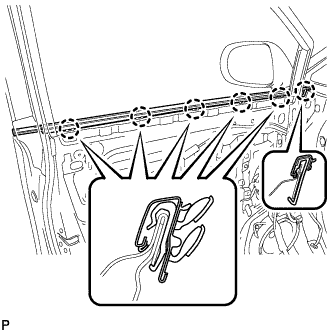
Engage the 5 clamps and install the electrical key wire harness.
-
Connect the connector.
-
-
INSTALL FRONT DOOR INSIDE LOCKING CABLE ASSEMBLY
-
Install the front door inside locking cable assembly.
-
Engage the 3 claws.
-
-
INSTALL FRONT DOOR LOCK REMOTE CONTROL CABLE ASSEMBLY
-
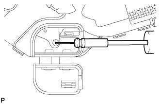
Install the front door lock remote control cable assembly.
-
-
INSTALL FRONT DOOR LOCK ASSEMBLY
Note
-
When reusing the removed front door lock assembly, replace the door lock wiring harness seal on the connector with a new one.
-
Do not allow grease or dust to adhere to the door lock wiring harness seal surface of the connector.
-
Reusing the door lock wiring harness seal or using a damaged door lock wiring harness seal may cause water intrusion. This may result in a malfunction of the front door lock assembly.
-
Apply MP grease to the sliding parts of the front door lock assembly.
-
Install a new door lock wiring harness seal to the front door lock assembly.
-
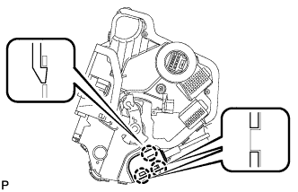
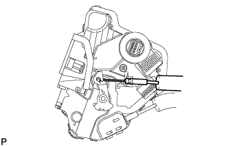
Insert the front door lock open rod to the front door lock assembly.
-
Make sure that the front door lock open rod is securely connected to the front door lock assembly.
-
Using a T30 "TORX" socket wrench, install the front door lock assembly with the 3 screws.
- Torque:
- 5.0 N*m { 51 kgf*cm, 44 in.*lbf }
-
-
INSTALL FRONT DOOR REAR OUTSIDE HANDLE PAD
-
Engage the 2 claws and install the front door rear outside handle pad.
-
-
INSTALL FRONT DOOR FRONT OUTSIDE HANDLE PAD
-
Engage the 3 claws and install the front door front outside handle pad.
-
-
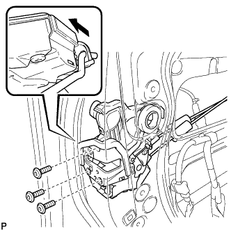
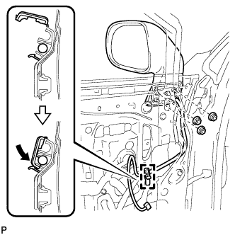
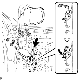
INSTALL FRONT DOOR OUTSIDE HANDLE ASSEMBLY
-
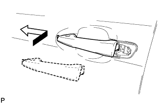
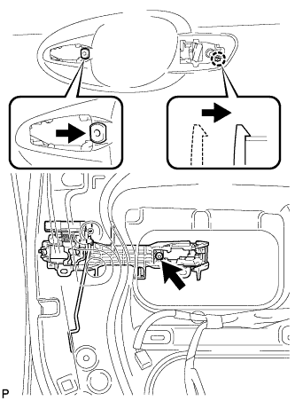
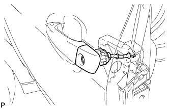
Insert the front end of the front door outside handle assembly into the front door outside handle frame.
-
Insert the rear end of the front door outside handle assembly into the front door outside handle frame, then slide the front door outside handle assembly toward the front of the vehicle to install it.
-
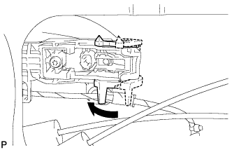
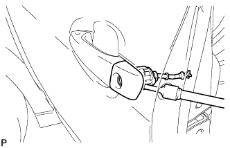
Move the lever back in the direction indicated by the arrow in the illustration to lock the door outside handle assembly.
-
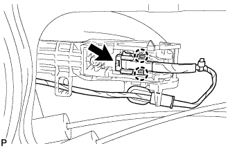
Connect the connector.
-
Engage the 2 claws.
-
-
INSTALL FRONT DOOR OUTSIDE HANDLE COVER (for Driver Side)
-
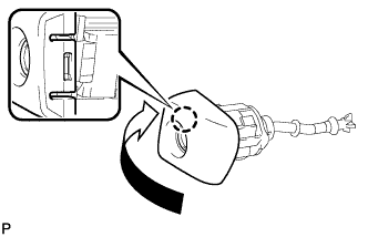
Engage the claw and install the front door outside handle cover to the front door lock cylinder.
-
-
INSTALL FRONT DOOR OUTSIDE HANDLE COVER (for Front Passenger Side)
-
Using a T30 "TORX" socket wrench, install the front door outside handle cover with the screw.
- Torque:
- 4.0 N*m { 41 kgf*cm, 35 in.*lbf }
-
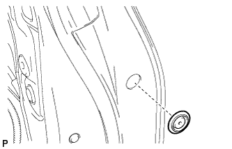
Install the hole plug.
-
-
INSTALL FRONT DOOR OUTSIDE HANDLE COVER WITH LOCK CYLINDER ASSEMBLY (for Driver Side)
-
Install the front door outside handle cover with lock cylinder assembly.
Tech Tips
Make sure that the front door lock cylinder rod is inserted into the front door lock assembly.
-
Using a T30 "TORX" socket wrench, install the front door lock cylinder with the screw.
- Torque:
- 4.0 N*m { 41 kgf*cm, 35 in.*lbf }
-
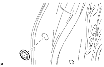
Install the hole plug.
-
-
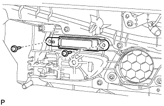
INSTALL FRONT DOOR REAR LOWER FRAME SUB-ASSEMBLY
-
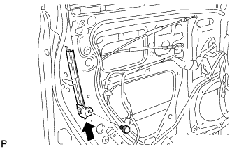
Install the front door rear lower frame sub-assembly with the bolt as shown in the illustration.
-
-
INSTALL FRONT DOOR GLASS RUN
-
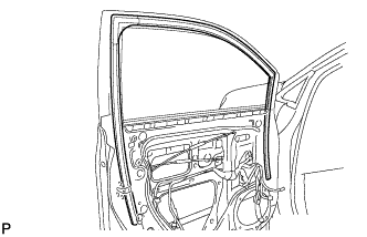
Install the front door glass run.
-
-
INSTALL FRONT POWER WINDOW REGULATOR MOTOR ASSEMBLY
Note
The regulator arm must be below the intermediate position when installing the power window regulator motor.
-
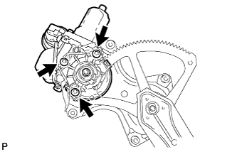
Using a T25 "TORX" socket wrench, install the front power window regulator motor assembly with the 3 screws.
- Torque:
- 5.4 N*m { 55 kgf*cm, 48 in.*lbf }
Tech Tips
A new front window regulator uses self-tapping screws to thread new installation holes when the self-tapping screws are inserted.
-
-
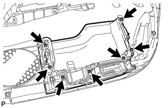
INSTALL FRONT DOOR WINDOW REGULATOR ASSEMBLY
-
Apply MP grease to the sliding parts of the front door window regulator assembly.
-
Install the temporary bolt to the front door window regulator assembly.
-
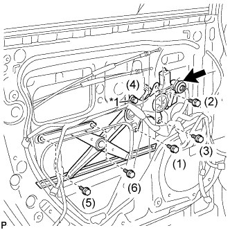
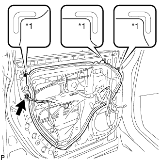
Text in Illustration *1 Temporary Bolt Temporarily install the front door window regulator assembly.
-
Tighten the temporary bolt and 5 bolts to install the front door window regulator assembly.
Tech Tips
Tighten the bolts in the order shown in the illustration.
- Torque:
- 8.0 N*m { 82 kgf*cm, 71 in.*lbf }
-
Connect the connector.
-
-
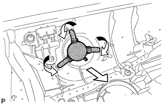
INSTALL FRONT DOOR GLASS SUB-ASSEMBLY
-
Connect the cable to the negative (-) battery terminal.
-
Connect the power window regulator master switch assembly and move the front door glass subassembly so that the door glass bolts can be seen.
-
w/ Navigation System for HDD:
Note
After the power switch is turned off, the display and navigation module display (HDD navigation system) records various types of memory and settings. As a result, after turning the power switch off, make sure to wait for the time specified in the following table before disconnecting the cable from the negative (-) battery terminal.
Waiting Time before Disconnecting Cable from Negative (-) Battery Terminal Specification Waiting Time w/o Telematics transceiver 60 sec. w/ Telematics transceiver 120 sec.
-
-
Disconnect the cable from the negative (-) battery terminal and power window regulator master switch assembly.
CAUTION:
Wait at least 90 seconds after disconnecting the cable from the negative (-) battery terminal to disable the SRS system Click here.
-
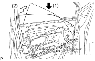
Insert the front door glass sub-assembly into the front door panel along the front door glass run as indicated by the arrows in the order shown in the illustration.
-
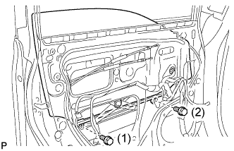
Install the front door glass sub-assembly with the 2 bolts.
- Torque:
- 5.5 N*m { 56 kgf*cm, 49 in.*lbf }
Tech Tips
Tighten the bolts in the order shown in the illustration.
-
-
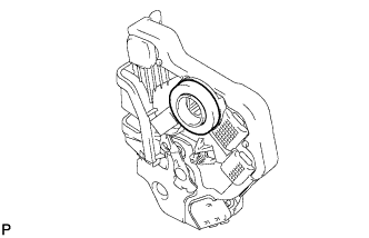
INSTALL OUTER REAR VIEW MIRROR ASSEMBLY
-
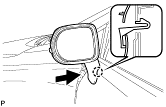
Engage the claw to install the outer rear view mirror assembly as shown in the illustration.
-
w/o Side Monitor System:
-
Install the 3 nuts.
- Torque:
- 5.5 N*m { 56 kgf*cm, 49 in.*lbf }
-
Engage the clamp as shown in the illustration.
-
-
w/ Side Monitor System:
-
Install the 3 nuts.
- Torque:
- 5.5 N*m { 56 kgf*cm, 49 in.*lbf }
-
Engage the clamp as shown in the illustration.
-
Connect the connector.
-
-
-
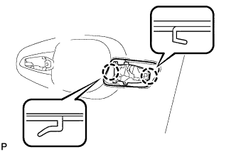
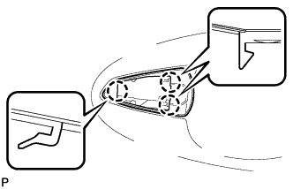
INSTALL OUTER MIRROR INSTALL HOLE COVER
-
Engage the 2 claws and 2 guides to install the outer mirror install hole cover as shown in the illustration.
-
-
INSTALL OUTER MIRROR PROTECTOR
-

Install a new outer mirror protector.
-
-
INSTALL FRONT DOOR SERVICE HOLE COVER
-
Apply butyl tape to the front door panel.
-
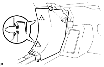
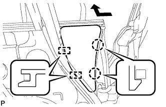
Text in Illustration *1 Reference Point Pass the front door lock remote control cable assembly and front door inside locking cable assembly through a new front door service hole cover.
-
Attach the front door service hole cover according to the reference points on the front door panel.
Note
Securely install the front door service hole cover preventing wrinkles and air bubbles.
-
Connect the connector.
-
-
INSTALL NO. 1 FRONT DOOR TRIM BRACKET
-
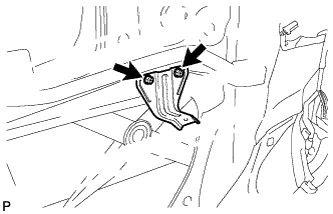
Install the 2 bolts and No. 1 front door trim bracket.
-
-
INSTALL OUTER MIRROR CONTROL ECU ASSEMBLY
-
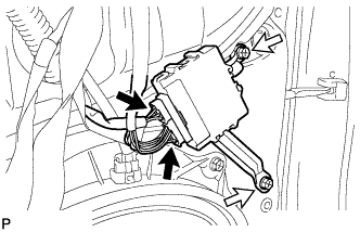
Install the outer mirror control ECU assembly with the 2 screws.
-
Connect each connector.
-
-
INSTALL FRONT NO. 1 SPEAKER ASSEMBLY
-
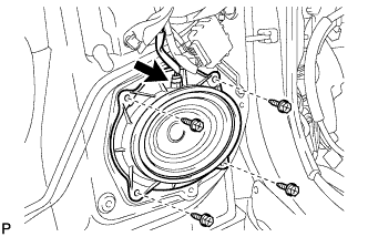
Install the front No. 1 speaker assembly with the 4 screws.
-
Connect the connector.
-
-
INSTALL FRONT NO. 3 SPEAKER ASSEMBLY
-
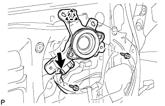
Engage the clip and temporarily install the front No. 3 speaker assembly.
-
Install the front No. 3 speaker assembly with the 2 screws.
-
Connect the connector.
-
-
INSTALL DOOR FRAME GARNISH
-
Install the door frame garnish with the 2 clips.
-
-
INSTALL FRONT DOOR TRIM POCKET
-
Install the front door trim pocket with the 7 screws.
-
-
INSTALL SEAT MEMORY SWITCH (w/ Seat Position Memory System)
-
Install the seat memory switch with the 2 screws.
-
-
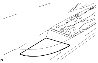
INSTALL FRONT DOOR SPEAKER GRILLE SUB-ASSEMBLY
-
Bend the claws as shown in the illustration to install the front door speaker grille sub-assembly.
-
-
INSTALL FRONT NO. 2 SPEAKER ASSEMBLY
-
Install the front No. 2 front speaker assembly with the 2 screws.
-
Engage the clamp.
-
-
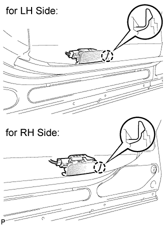
INSTALL FRONT DOOR INNER GLASS WEATHERSTRIP
-
Engage the 4 claws and install the front door inner glass weatherstrip as shown in the illustration.
-
-
INSTALL FRONT DOOR TRIM BOARD SUB-ASSEMBLY
-
Install a new front door trim board retainer (green).
-
Connect the front door lock remote control cable assembly and front door inside locking cable assembly.
-
Connect each connector.
-
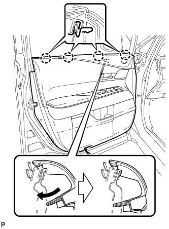
Engage the front door trim board sub-assembly with the 4 claws of the front door inner glass weatherstrip as shown in the illustration.
-
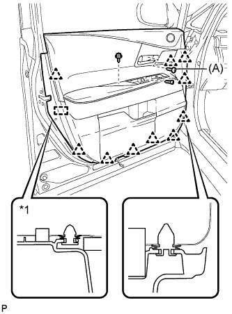
Text in Illustration *1 Front Door Trim Board Retainer Engage the 10 clips, front door trim board retainer and install the front door trim board sub-assembly.
-
Install the 3 screws.
- Torque:
- (A)
- 3.5 N*m { 36 kgf*cm, 31 in.*lbf }
-
-
INSTALL NO. 1 FRONT DOOR STIFFENER CUSHION
-
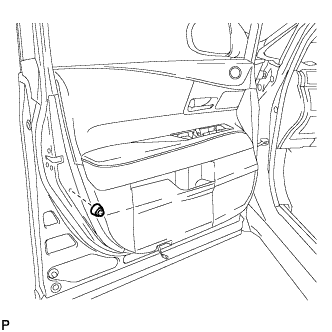
Install the No. 1 front door stiffener cushion with the screw.
-
-
INSTALL COURTESY LIGHT ASSEMBLY
-
Connect the connector.
-
Engage the claw to install the courtesy light assembly.
-
-
INSTALL DOOR ARMREST COVER
-
Install the door armrest cover.
-
-
INSTALL POWER WINDOW REGULATOR MASTER SWITCH ASSEMBLY WITH FRONT DOOR ARMREST BASE PANEL (for Driver Side)
-
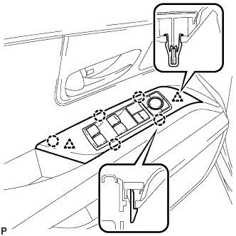
Connect the connector.
-
Engage the 2 clips and 5 claws, and install the power window regulator master switch assembly with front door armrest base panel.
-
-
INSTALL POWER WINDOW REGULATOR SWITCH ASSEMBLY WITH FRONT DOOR ARMREST BASE PANEL (for Front Passenger Side)
-
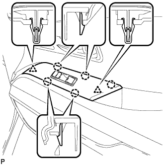
Connect the connector.
-
Engage the 2 clips and 5 claws, and install the power window regulator switch assembly with front door armrest base panel.
-
-
INSTALL FRONT DOOR INSIDE HANDLE BEZEL PLUG
-
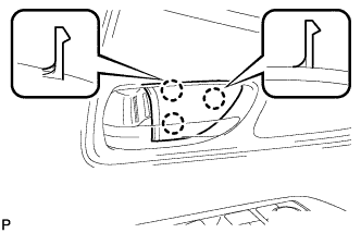
Engage the 3 claws and install the front door inside handle bezel plug.
-
-
INSPECT FRONT DOOR
-
Check that the clearance measurements of areas *1 through *32 are within each standard range.
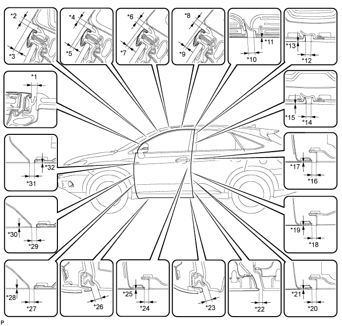
Standard Clearance Area Measurement Area Measurement *1 3.5 to 6.5 mm (0.138 to 0.256 in.) *2 3.5 to 6.5 mm (0.138 to 0.256 in.) *3 3.7 to 6.7 mm (0.146 to 0.264 in.) *4 3.5 to 6.5 mm (0.138 to 0.256 in.) *5 2.0 to 5.0 mm (0.0787 to 0.197 in.) *6 3.5 to 6.5 mm (0.138 to 0.256 in.) *7 1.2 to 4.2 mm (0.0472 to 0.165 in.) *8 3.5 to 6.5 mm (0.138 to 0.256 in.) *9 0.5 to 3.5 mm (0.0197 to 0.138 in.) *10 5.5 mm (0.217 in.) *11 -1.5 to 1.5 mm (-0.0591 to 0.0591 in.) *12 3.0 to 6.0 mm (0.118 to 0.236 in.) *13 -1.5 to 1.5 mm (-0.0591 to 0.0591 in.) *14 3.0 to 6.0 mm (0.118 to 0.236 in.) *15 -1.5 to 1.5 mm (-0.0591 to 0.0591 in.) *16 3.2 to 6.2 mm (0.126 to 0.244 in.) *17 -1.5 to 1.5 mm (-0.0591 to 0.0591 in.) *18 3.2 to 6.2 mm (0.126 to 0.244 in.) *19 -1.5 to 1.5 mm (-0.0591 to 0.0591 in.) *20 3.2 to 6.2 mm (0.126 to 0.244 in.) *21 -1.5 to 1.5 mm (-0.0591 to 0.0591 in.) *22 3.0 to 7.0 mm (0.118 to 0.276 in.) *23 5.5 to 10.5 mm (0.217 to 0.413 in.) *24 3.2 to 6.2 mm (0.126 to 0.244 in.) *25 -1.5 to 1.5 mm (-0.0591 to 0.0591 in.) *26 5.5 to 10.5 mm (0.217 to 0.413 in.) *27 2.8 to 5.8 mm (0.110 to 0.228 in.) *28 -1.5 to 1.5 mm (-0.0591 to 0.0591 in.) *29 2.8 to 5.8 mm (0.110 to 0.228 in.) *30 -1.5 to 1.5 mm (-0.0591 to 0.0591 in.) *31 2.8 to 5.8 mm (0.110 to 0.228 in.) *32 -1.5 to 1.5 mm (-0.0591 to 0.0591 in.)
-
-
ADJUST FRONT DOOR
-
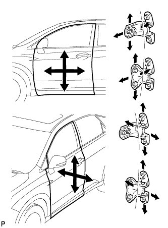
Using SST, loosen the hinge bolts on the vehicle body and adjust the door position.
- SST
- 09812-00010
-
Tighten the hinge bolts on the vehicle body after the adjustment.
- Torque:
- 26 N*m { 265 kgf*cm, 19 ft.*lbf }
-
Loosen the hinge bolts on the door and adjust the door position.
-
Tighten the hinge bolts on the door after the adjustment.
- Torque:
- 27 N*m { 275 kgf*cm, 20 ft.*lbf }
-
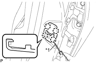
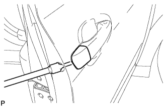
Text in Illustration *1 Protective Tape Using a screwdriver, disengage the 4 claws and remove door lock striker cover.
Tech Tips
Tape the screwdriver tip before use.
-
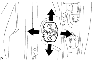
Using a T40 "TORX" socket wrench, slightly loosen the striker mounting screws.
-
Using a brass bar and a hammer, hit the striker to adjust its position.
-
Using a T40 "TORX" socket wrench, tighten the striker mounting screws after the adjustment.
- Torque:
- 23 N*m { 235 kgf*cm, 17 ft.*lbf }
-
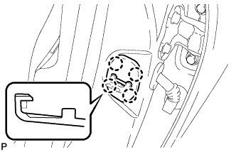
Engage the 4 claws and install the door lock striker cover.
-
-
CONNECT CABLE TO NEGATIVE BATTERY TERMINAL
Note
When disconnecting the cable, some systems need to be initialized after the cable is reconnected Click here.
-
INSTALL REAR DECK FLOOR BOX
-

Install the rear deck floor box with the 3 clips.
-
-
INITIALIZE POWER WINDOW CONTROL SYSTEM
-
INSPECT SRS WARNING LIGHT
-
ADJUST SIDE TELEVISION CAMERA OPTICAL AXIS (CAMERA POSITION SETTING) (w/ Side Monitor System)